background image

AUGER MAINTENANCE

In some installations the water supply to the ice

maker will be so concentrated with dissolved

minerals, (such as calcium carbonate) that as ice is

made, the evaporator and auger become coated

with those minerals, requiring a more frequent

cleaning than twice per year. If in doubt about the

condition of the evaporator and auger, the auger

can be removed so the parts can be inspected.

Note: Water filters can filter out suspended solids,

but not dissolved solids. “Soft” water may not be

the complete answer. Check with a water

treatment specialist regarding water treatment.

Switch off electrical power, and shut off the water

supply.

For more information on removal of these parts,

see REMOVAL AND REPLACEMENT.

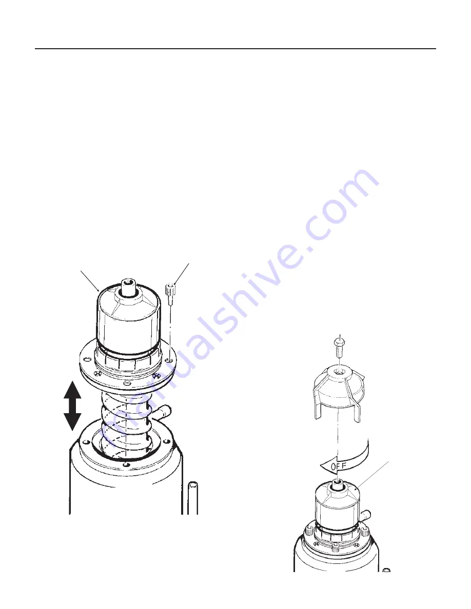
1. To remove the auger, remove front and top

panel. See Removal And Replacement.

2. Push bail clamp back and remove ice chute

cover.

3. Unscrew and remove ice sweep.

4. Remove ice chute from evaporator.

5. Remove 4 allen head screws holding breaker to

evaporator.

6. Pull up on breaker to remove auger.

Allow the auger to dry, the stainless steel of the

auger and evaporator must be clean and bright.

Clean the auger and evaporator as required. DO

NOT HONE THE EVAPORATOR.

7. Replace the water seal.

8. Reverse to reassemble.

Double System RL

November 2000

Page 17

Note:

Flaker Components Shown, Nugget

Components are Similar

DIVIDER, AUGER

AND SLOTTED

COLLAR

ALLEN HEAD

SCREWS

BREAKER

COVER

Summary of Contents for Double System RL

Page 1: ... List Page 6 INITIAL START UP Page 7 COMPONENT IDENTIFICATION Page 8 COMPONENT DESCRIPTION Evaporator Page 9 CONTROL BOX Components Page 10 ELECTRICAL SEQUENCE Page 11 OPERATION Page 12 OPERATION Refrigeration Page 13 CLEANING and SANITATION Page 14 SENSOR MAINTENANCE Page 15 BEARING MAINTENANCE Page 16 AUGER MAINTENANCE Page 17 SERVICE DIAGNOSIS Page 18 SERVICE DIAGNOSIS Page 19 CONTROL SYSTEM DI...

Page 2: ... been altered in any way including the use of any parts and or other components not specifically approved by Scotsman Scotsman reserves the right to make design changes and or improvements at any time Specifications and designs are subject to change without notice Double System RL January 2004 Page 2 15 53 3 1 SUCTION LINE CONNECTION 7 8 LIQUID LINE CONNECTION 1 2 20 84 9 43 5 25 3 17 8 18 8 21 66...

Page 3: ...8 2 5 cap screws Level the assembly by a Turning the leg levelers in or out on the standard legs b Use shims under the heavy duty legs of the KLP4 Locate the Nameplate The nameplate is located on the back panel of the machine and contains the electrical characteristics particular to the unit being installed Refrigeration Installation The skills of a refrigeration technician are required to connect...

Page 4: ...ram The ice machine should be connected to it s own electrical circuit and be individually fused Voltage when the unit is under full load must remain within the limitations listed on page 2 LOW VOLTAGE CAN CAUSE EQUIPMENT MALFUNCTION AND OR DAMAGE All external wiring should conform to the National State and local electrical codes Usually the services of a licensed electrician will be required Doub...

Page 5: ... the ice maker and the water supply Drain System All drains are of the gravity type and must have a minimum of 1 4 fall per foot of horizontal run The drains must be installed to conform to local plumbing codes The use of a vent at the machine and at the bin will allow the system to drain properly Use only rigid tubing for drains insulation of the bin drain is recommended Double System RL November...

Page 6: ...oved from inside the cabinet 6 Have the electrical connections been made 7 Have the drains been installed and checked for leaks 8 Has the refrigeration supply been installed and checked for leaks 9 Has the bin and cabinet been wiped clean or sanitized 10 Has the warranty registration card been properly filled out and mailed to Scotsman 11 Has the owner been given the service manual and been instru...

Page 7: ...ir and the float drops letting in more water 7 Switch on the other master mode switch observe that The liquid line valve opens The gearmotor runs Within a short time that side of the machine begins to make ice Water flows from the water reservoir and the float drops letting in more water 8 With both sides operating the sight glass should remain full and the low side pressure will be about model ty...

Page 8: ...orator outlet at the TXV bulb and check the low side pressure at the EPR valve Convert the pressure to temperature using a temperature pressure chart and subtract the amount from the outlet temperature The result is the superheat Use an electronic thermometer EPR Evaporator Pressure Regulator Valve This valve maintains a constant pressure on its inlet evaporators side regardless of the pressure on...

Page 9: ...here the two seal faces meet Ice Sweep A plastic cap with fingers It revolves with the auger to sweep the ice into the ice chute Divider only on FM or FME Where the ice is compressed and much of the extra water is squeezed out of it before it is discharged into the bin Motor A split phase motor that drives the gear reducer Bearing As the ice is pushed up the evaporator the auger is thrust down and...

Page 10: ... for the gear motor with a built in time delay to clear the evaporator of ice when the unit turns off and for the liquid line valve See photo below On Off Mode Switch Manual control for that side of the machine Double System RL November 2000 Page 10 LED1 Power Light Freeze Light Bin Full Light Water OK Light Service Light LED3 Control Board Auger Relay Compressor Relay ...

Page 11: ...he bin full light glows and the machine shuts down Shut Down The compressor relay opens LED1 goes out The liquid line valve closes The refrigerant flow stops The auger motor stays on for 1 more minute clearing out ice in the evaporator and then The auger motor relay opens LED3 goes out and the auger motor stops The liquid line valve will not re open until 2 minutes or more have passed after the la...

Page 12: ... it enters through the float valve The water then goes out the bottom of the reservoir tank to the bottom of the evaporator Reservoir overflow or evaporator condensation is routed to the drain Double System RL November 2000 Page 12 WATER INLET RESERVOIR ICE CHUTE WATER LEVEL EVAPORATOR WATER INLET DRIP PAN DRAIN WATER SCHEMATIC ...

Page 13: ...hermostatic expansion valve meters the liquid refrigerant into the evaporator where it boils off evaporates and absorbs heat It then moves through the ball valve and into the evaporator pressure regulator valve or EPR The EPR keeps the evaporator pressure above a predetermined point even though the suction line pressure of the remote high side system may vary The refrigerant now a low pressure gas...

Page 14: ...s been added to the reservoir and the reservoir is nearly empty switch the master switch to OFF 11 After draining the reservoir as in step 6 wash and rinse the water reservoir 12 Go thru steps 13 19 to sanitize the ice machine water system 13 Mix two gallons of sanitizer solution Use an approved sanitizer A possible sanitizer solution may be obtained by mixing two gallons of warm 90 115o F potable...

Page 15: ...and wipe the inside clean as illustrated 2 The ice machine senses water level by a probe located in the water reservoir At least twice a year the probe should be removed from the reservoir and the tip wiped clean of mineral build up Double System RL November 2000 Page 15 CLEAN THE ICE LEVEL CONTROL SENSORS SLIDE ICE LEVEL CONTROLS OUT OF CHUTE Clean the Probe s Tip with ice machine cleaner and a c...

Page 16: ...o check the action of the bearing It should rotate smoothly To remove the breaker take out all four allen head cap screws and pull the breaker off the auger and evaporator If the bearing only needs grease inject grease into the bearing using Scotsman grease needle pn 02 3559 01 and Scotsman bearing grease cartridge pn A36808 001 Be sure to inject grease evenly and thoroughly See Removal and Replac...

Page 17: ...ff electrical power and shut off the water supply For more information on removal of these parts see REMOVAL AND REPLACEMENT 1 To remove the auger remove front and top panel See Removal And Replacement 2 Push bail clamp back and remove ice chute cover 3 Unscrew and remove ice sweep 4 Remove ice chute from evaporator 5 Remove 4 allen head screws holding breaker to evaporator 6 Pull up on breaker to...

Page 18: ...ings gear motor condition and scale on auger evaporator May also be due to liquid line valve leak thru during the off cycle Check valve Auger not turning Due to motor failure auger relay failure on circuit board or gears stripped Check drive train Low suction pressure Liquid line valve not opening due to coil failure or failure of compressor relay on circuit board EPR setting too low check adjust ...

Page 19: ... shut off the water remove the auger replace the water seal Check gear motor for water infiltration Uses too much water Reservoir float valve leaks thru Replace float valve or seat Excessive ice meltage Bin drain clogged Clean out bin drain Improper installation of drains they are connected Drains must be separate Poor fit between bin door and door frame Adjust or replace Machine makes too much no...

Page 20: ... to the wire where the water sensor plugs into and place the other end in the water The water OK light should go ON If it does not replace the control board 3 Ice sensor check Is the Bin Full light Off If it is OFF and the Service light is Off and the unit is not running replace the control board If it is OFF and the auger motor is running but the compressor is not check the compressor contactor c...

Page 21: ... reservoir from ice maker 8 Reverse to reassemble BIN CONTROLS Ice Level Sensors 1 Disconnect electrical power 2 Remove front panel 3 Remove control box cover 4 Locate ice chute at the base of the chute in front of and behind it are two plastic bin control mounts 5 Slide each bin control to the left and in the control box disconnect the electrical leads connecting the bin control to the circuit bo...

Page 22: ... a The bearing is pressed into the breaker to remove the bearing and replace it an arbor press is needed b Replace lower seals before installing new bearing in breaker Note seals must be pressed in with a tool pushing against the outer edge only they will not install by hand Replace parts as required Re grease bearing with Scotsman part no A36808 001 bearing grease Replace top seal and check the o...

Page 23: ... evaporator d Lift up and remove breaker from evaporator e If the auger is stuck use a slide hammer type puller to pull on the auger at the threaded hole The size of that hole is 5 8 18 Inspect the auger the critical areas of the auger are 1 The auger body It should be clean and shining Sometimes an auger will appear clean when wet but after it is dry it will be seen to be stained Scrub the auger ...

Page 24: ... the water seal that rotates with the auger must also be replaced Remove the old part from the auger and clean the mounting area 4 Place a small bead of food grade silastic sealant such as 732 RTV or Scotsman part number 19 0529 01 on the area of the auger where the water seal is to be mounted 5 Carefully push the water seal rubber side against the auger shoulder and the silastic CAUTION Do not ge...

Page 25: ...at in the new evaporator at the old connections 6 Install an new drier in the liquid line 7 Evacuate the system until dehydrated then weigh in the nameplate charge Check for leaks 8 Install auger breaker breaker bearing assembly and ice discharge chute in reverse order of disassembly See To Reassemble Evaporator and Auger To Reassemble the Evaporator and Auger 1 After the gearmotor has been inspec...

Page 26: ...eck the gears and bearings They are likely to be fine if the oil is If there is evidence of water in the oil rusty bearings and gears the oil having a creamy white appearance oil level too high carefully inspect the bearings and gears If in doubt about the condition of a part replace it The oil quantity is 14 fluid ounces do not overfill Note The gears and bearings are available only as pressed to...

Reviews: