background image

Location & Assembly

Air cooled models take room temperature air in

from the sides and discharge warm air out the

back. Do not place them where the heat and noise

will be objectionable.
A 6 inch

MINIMUM

clearance on the back, and

both sides is required for the basic operation and

service of the air cooled model.

Note: A six inch side clearance with zero top

clearance will NOT provide enough air exchange

space for optimum performance. 12 inches side

clearance is required when there is no top

clearance.

Unpacking and Assembly:

Begin with unpacking the ice storage bin. Remove

the carton, and using part of the carton as a

cushion, tip the bin on its back to remove the skid

and attach the legs or casters.
Note: Stacked applications may not use casters.

Return the bin to an upright position. Check the bin

top gasket for gaps and tears, fill any in with food

grade sealant prior to placing the ice machine on

the bin.

Level the top edge of the bin front to back and

left to right.

If the ice machine has not been unpacked, do so

now. Remove the carton from the skid. After

removal of the shipping straps, lift the ice machine

off the skid directly onto the bin.
Note: The machine is heavy! Use a mechanical

hoist if necessary.

Secure the ice machine to the bin with the

hardware provided (two metal straps and 4 bolts).

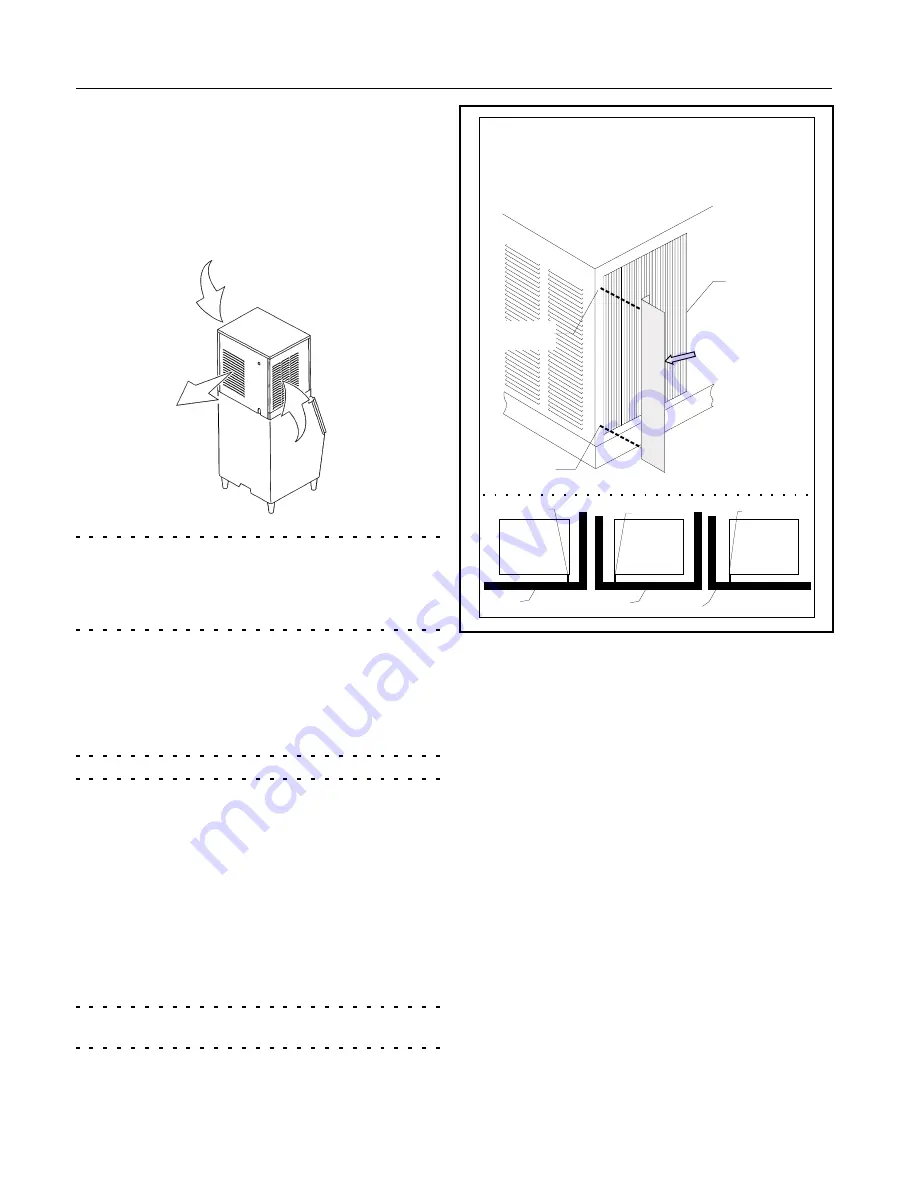
Air cooled models come equipped with a baffle

that can be used when the machine is installed

in a corner.

The purpose of the baffle is to limit air

recirculation. This can occur in a corner when the

hot air from the back of the machine is re-drawn

back into the machine from the nearest side of the

machine.
Install the air baffle as shown. Place the baffle:

On the left rear corner when the left wall and

back wall are between 6 and 18 inches from

the unit.

On the right rear corner when the right wall

and back are between 6 and 18 inches from

the unit.

CME1056

May 2000

Page 6

Air

Baffle

Back View of Ice

Machine

Remove Air Baffle from its

Shipping Position.

Air Cooled

Condenser

Outlet

17-2632-01 Rev. A.

Attach Air

Baffle Here

Baffle Position

Baffle

Baffle

Ice Machine

Top View

Ice Machine

Top View

Ice Machine

Top View

Wall

Wall

Wall

Use baffle for

In-The-Corner Applications

Attach Air

Baffle Here

Airflow is in

the sides and

out the back

Summary of Contents for CME1056

Page 1: ...ing Water Cooled PAGE 12 Electrical PAGE 13 After Utility Connections PAGE 14 Component Description and Function PAGE 15 AutoIQ Controller PAGE 16 How To Operate The Controller PAGE 17 Initial Start Up PAGE 18 Adjustments PAGE 19 How This Machine Works PAGE 20 How This Machine Works PAGE 21 Technicians Only Freeze Cycle Operational Sequence PAGE 22 Technicians Only Harvest Cycle Operational Sequen...

Page 2: ...o not deploy the CME1056 s thermostat Lancer 30 wide dispenser Add adapter kit KSTAT MD Cornelius ED200 dispenser requires adapter kit from Cornelius Do not deploy the CME1056 s thermostat Other combinations may be available See Scotsman product literature for more information Stacking two CME1056s together requires stacking kit KSCME6 MD cannot stack any other model with a CME1056 Scotsman reserv...

Page 3: ... Layout MINIMUM FOR AIR VENTILATION 6 00 in 15 2 cm ICE OPENING 18 70 in 47 5 cm 1 63 in 4 1 cm 2 70 in 6 9 cm 9 85 in 25 0 cm PLAN VIEW 6 00 in 15 2 cm 6 00 in 15 2 cm ICE MINIMUM FOR AIR VENTILATION MINIMUM FOR UTILITY CONNECTIONS OPENING ...

Page 4: ...2 cm 2 70 in 6 9 cm PLAN VIEW CONDENSER INLET 3 8 F P T CONDENSER DRAIN 1 2 F P T 26 35 in 66 9 cm 23 06 in 58 6 cm 10 25 in 26 0 cm 15 53 in 39 4 cm 88 DIA KNOCKOUT ELECTRICAL INLET WATER INLET 3 8 FLARE 17 68 in 44 9 cm 4 31 in 10 9 cm 21 75 in 55 2 cm 2 38 in 6 0 cm 4 75 in 12 1 cm 10 75 in 27 3 cm SUMP DRAIN 3 4 F P T BACK VIEW 24 00 in 61 0 cm SIDE VIEW ...

Page 5: ...up the machine That water rinse combined with water filters prolongs the times between needed water system cleaning Note All Scotsman CM3 models like those described in this manual feature Scotsman s AutoIQ control system and ReliaClean water system cleaning process Service Technicians All models covered here come set from the factory at a standard water rinse which is compatible with typical wate...

Page 6: ...ow Remove the carton from the skid After removal of the shipping straps lift the ice machine off the skid directly onto the bin Note The machine is heavy Use a mechanical hoist if necessary Secure the ice machine to the bin with the hardware provided two metal straps and 4 bolts Air cooled models come equipped with a baffle that can be used when the machine is installed in a corner The purpose of ...

Page 7: ...he front panel to the machine then pull out at the bottom 2 Lift up at the front edge and push the top panel back until it releases from the tabs connecting it to the back panel 3 Remove the screws at the front edge of the left side panel and pull forward until it releases from the tabs connecting it to the back panel CME1056 May 2000 Page 7 Remove The Front Panel First ...

Page 8: ... onto the bottom one Secure together with hardware from the top machine Remove front and left side panels Upper Machine 8 Knock out 1 hole in the lower left viewed from the front corner of the upper unit s back panel Lower Unit 9 Knock out 1 hole in the upper left viewed from the front corner of the lower unit s back panel 10 Position the strain reliefs over the wrapped portion of the stacking kit...

Page 9: ...b of the thermostat to the bracket from the kit 16 Install the bin thermostat bracket onto the bottom of the machine 17 Pull back excess cap tube and coil up in the machine 18 Connect wires from harness to thermostat terminals Both Machines 19 Return all panels and covers to their normal positions 20 Complete the balance of the installation CME1056 March 1999 Page 9 Stacking ...

Page 10: ...ir 3 Locate bin thermostat bracket 4 Carefully position the thermostat bulb on the bracket 5 Fasten the bracket to the bottom of the ice machine with the two 3 pronged knobs supplied with the unit 6 Pull back into the ice machine any excess capillary tubing 7 Return the baffle to the bin and continue with the installation Bin Thermostat Altitude Correction Table CW Turns of Range Screw under plast...

Page 11: ... flow at least 2 7 GPM or they will cause severe operational issues Check with the filter manufacturer When replacing a prior ice machine do NOT assume that the water flow capacity of the filter will be adequate All Drain Tubing Material must be RIGID Flexible tubing will eventually cause a restricted drain Drain Air cooled models have 1 gravity drain connection a 3 4 FPT fitting at the back of th...

Page 12: ... prior ice machine do NOT assume that the water flow capacity of the filter will be adequate All Drain Tubing Material must be RIGID Flexible tubing will eventually cause a restricted drain Drain Water cooled models have TWO gravity drain connections a 3 4 FPT fitting AND a FPT fitting Use only RIGID TUBING Flexible tubing may be easily kinked or become cracked The reservoir drain must be vented a...

Page 13: ...or HACR type circuit breakers may be used Electrical connections are made in the junction box in the back of the cabinet 1 Remove the junction box cover 2 Knock out 1 hole for a field supplied strain relief 3 Install wires and strain relief per code 4 Connect to wires and secure ground wire to ground screw inside the junction box Follow all Local State and National codes CME1056 May 2000 Page 13 P...

Page 14: ...ere it can receive adequate cooling air ____3 Has the correct electrical power been supplied to the machine ____4 Have all the water supply connections been properly made ____5 Have all the drain connections been properly made ____6 Has the unit been leveled ____7 Have all unpacking materials been removed ____8 Has the bin control been installed ____9 Is the water pressure adequate ____10 Have the...

Page 15: ... fully insulated for maximum efficiency Cube Deflector The slots in the inclined deflector allows the water falling from the evaporators back into the reservoir but when ice falls during harvest the ice slides off the deflector into the bin Refrigeration Service Access Valves Only to be used by a certified technician Allows access to the refrigeration system for diagnostic information Water Pump F...

Page 16: ...m the evaporators The compressor fan motor if air cooled and water pump are ON Harvest The refrigeration and water systems are operating to harvest the ice cubes While the compressor is on for the full cycle the water pump will be off at the beginning and inlet water valve will switch off before the end Clean The Inlet Water Valve opens to fill the reservoir The Water Pump starts The Clean indicat...

Page 17: ...ll switch off immediately To Reset Machine machine off error light on First push and release the Off button then push and release the Freeze button Diagnostic Light Recall To recall the last error on the blue housing CM3 controller 1 Switch the unit OFF by holding the OFF button for longer than 3 seconds 2 Hold the Off button down again until the Purge Setting indicators Green Lights are on 3 Push...

Page 18: ...less than 40 seconds The purge valve closes and the Inlet water valve will open for a short time to add water The Bin Full indicator light will go on and off as ice falls from the evaporators 6 Machines are shipped from the factory with the purge level set to accommodate average water conditions To achieve optimal machine performance set the purge level to the minimum setting Note While the amount...

Page 19: ...alve is properly set Thermostatic Expansion Valve The TXV is not adjustable do not attempt to adjust it How to Adjust the Amount of Water Purge Adjustment is done by use of the control buttons on the AutoIQ Controller Examine the next section to become familiar with the AutoIQ Controller before beginning 1 If the machine is on push and hold the OFF button for more than 3 seconds then release it Th...

Page 20: ...and back into the reservoir As water is turned into ice the water level in the reservoir falls and at the point where the cubes are fully formed the Water Level Sensor indicates to the AutoIQ Controller that it is time to begin the Harvest cycle During the Harvest cycle water again enters the water reservoir and a purge valve opens to drain the reservoir and dilute the concentration of accumulated...

Page 21: ...xpansion Valve it enters the top of the evaporators and ice will form at the top first When cubes need to be released Harvest the Hot Gas Valve is opened and Hot discharge gas flows directly from the compressor to the evaporator inlets This warms up the evaporators and the surface of the ice frozen to the evaporator surface melts Ice then falls into the bin CME1056 May 2000 Page 21 Condenser Evapo...

Page 22: ...r the water level If the water level does not fall the machine Shuts Down on a Water Error 7 Once per cycle the machine will shut off the water pump It only does this when the water temperature reaches a preset minimum The pump will only be off for a few seconds After the pump restarts the inlet water valve opens to refill the reservoir 8 As the machine makes ice the water level in the reservoir w...

Page 23: ...ose units so equipped In normal ambients the thermostat will react to ice on the bulb in a few seconds Reaction after removal will take about a minute under normal conditions and longer in colder rooms Stacked Units If the bottom unit is in harvest and receives a signal from the top unit that it is also in Harvest the bottom unit will stay in harvest for about 6 minutes If the bottom unit is shut ...

Page 24: ... has circulated for 10 minutes push and release the Clean button This starts the rinsing process The Clean indicator light will be ON Note The rinse process flushes any residual cleaner out of the ice machine s water system 10 Continue the rinsing process for 20 minutes then push the off button to switch the machine off 11 Go to the next step to sanitize the machine or go to step 19 to finish the ...

Page 25: ...porator and clean de mineralize them outside of the ice machine 1 Remove front panel 2 Push and release the OFF button 3 Remove the evaporator cover 4 Lift up at the center of the water distributors and disconnect the distributors from the manifold 5 Repeat for all evaporators and distributors 6 Examine the top of the evaporators The Water Distribution Channels must be free from mineral build up I...

Page 26: ... of the brackets there are two sensors in each bracket check that they are clear of mineral build up They may be wiped clean with ice machine cleaner to assist in removal of the build up Be sure to drain the reservoir or go thru a Clean cycle to remove residual cleaner Note Do NOT use abrasive materials or cleaner on the bin sensor lenses A soft toothbrush is an effective tool for cleaning these s...

Page 27: ...rge tube out of the reservoir and place it in the cup 4 Push and release the Harvest button 5 If working properly the water valve will fill a 16 oz cup in about 3 seconds Be prepared to push the Off button If it does not the water valve inlet or other water device is restricted To Check the Inlet Water Valve Screen 1 Disconnect the electrical power 2 Shut off the water supply 3 Remove the front pa...

Page 28: ...et hose of a vacuum cleaner in the condenser shroud B While the vacuum cleaner is on blow compressed air from the back of the condenser thru the fins C If grease is present use coil cleaner on the condenser Be sure to wipe up any excess coil cleaner 7 Additional access can be gained by removing the top of the fan shroud see page 34 8 After cleaning return all panels except the right front to their...

Page 29: ...he water inlet valve for proper water flow Water pump malfunction Check that pump hose is attached and if pump is plugged in and working Water level not sensed or not high enough Check harness from sensor Unit is off Refrigeration diagnostic light is ON or BLINKING Low discharge or long freeze cycle If the Refrigeration light is glowing steadily there is a probable refrigeration problem Harvest pr...

Page 30: ...y condenser or filter Replace filters clean condenser Recirculation of air Block air re circulation or move condenser Low refrigerant charge Check system If there is a low charge find the leak recover the refrigerant repair the leak replace the dryer evacuate and weigh in the nameplate charge Too much water Check for inlet water valve leak thru Unit does not shut off or cannot sense ice falling Ic...

Page 31: ...onnections if ok replace AutoIQ Controller Hot Gas Valve leaks thru warm tube temperatures on both sides of valve during freeze Mechanical problem in valve Replace valve Water Inlet Valve does not open Open solenoid coil Replace valve Stuck valve Replace valve No power to valve early part of harvest Check wire connections if ok replace AutoIQ Controller Water Inlet Valve does not flow enough water...

Page 32: ...temperature changes When the PTCR is cold it connects full current to the compressor s start winding After a very short time the PTCR heats up and shuts off the current flow Under normal conditions the PTCR s case is at about 180o F At that temperature the PTCR has very high resistance and will not allow current to flow It must cool down to about 120o F Before current will pas through it again Dia...

Page 33: ...ter Suction End of Freeze 24 to 30 PSIG 32 to 38 PSIG Suction Peak in Harvest 80 to 100 PSIG 105 to 125 PSIG Discharge 5 minutes into Freeze 195 to 215 PSIG 255 to 275 PSIG Discharge Minimum in Harvest 155 to 175 PSIG 190 to 210 PSIG Water Cooled 70o F indoor air 50o F water 90o F indoor air 70o F water Suction End of Freeze 22 to 28 PSIG 26 to 32 PSIG Suction Peak in Harvest 75 to 95 PSIG 80 to 1...

Page 34: ...6 Reach into cube port area and pull each sensor in and out of its installed position 7 Trace wire back to the controller and unplug 8 Reverse all steps to reassemble Water Temperature Sensor Note This sensor is replaced as a set with the Discharge Temperature Sensor 1 Remove left side and front panel 2 Push and release Off button 3 Remove 1 plastic bolt and the reservoir cover 4 Locate water temp...

Page 35: ...of the compressor 6 from the compressor discharge port 4 Unwrap the insulation and un snap the clip holding the sensor to the discharge line 5 Trace the sensor wires back to the controller they are plugged into 5 with the water temperature sensor and must be replaced with it 6 Reverse to replace be sure that the discharge line sensor is 6 up from the compressor discharge port Be sure to re wrap th...

Page 36: ...ust be used to locate refrigerant leaks C An HFC type liquid line dryer must be used D A nitrogen purge is required when brazing E When evacuating use of an electronic micron gage is recommend Evacuate to 300 microns F It must be liquid charged 1 Place a drum or cylinder of R 404A on the scale liquid out side up check container 2 Attach the charging hose to the cylinder of R 404A Open the cylinder...

Page 37: ...ne should start in a few minutes To Manually Reset the machine 1 Remove the front panel 2 Locate the AutoIQ Controller If a red diagnostic light is glowing note which one and its blink rate Then push and release the off button 3 Push and release the Freeze button 4 The machine should begin to operate If there is a lack of water it will soon shut off again 5 Return the front panel to its normal pos...

Reviews: