SCOPE COMMUNICATIONS UK LTD
PAGETEK PRO MK2
Ref: PTPROMK2INSTALLred
Page
13
of 27
Issue 1
4) System Power Up
a) Before powering up the system, check that the antenna is correctly fitted and that the
mains input wires are securely terminated to the appropriate Live, Neutral and Earth inputs
with no exposed strands of wire. An earth continuity check should be undertaken between
the mains earth and the system cabinet, checking the points indicated on diagram 6.
b) Perform a continuity check to establish that all used inputs are in the closed state and
check that all unused inputs have shorting links fitted.
b) Fit the black battery lead to the negative terminal of the battery. This will activate the
system and the front panel display will state “MAINS FAILURE” on the top line, briefly
followed by “Version 1.XX” on the bottom line, which denotes the firmware revision. The
yellow fault LED will light and the warning sounder will beep.
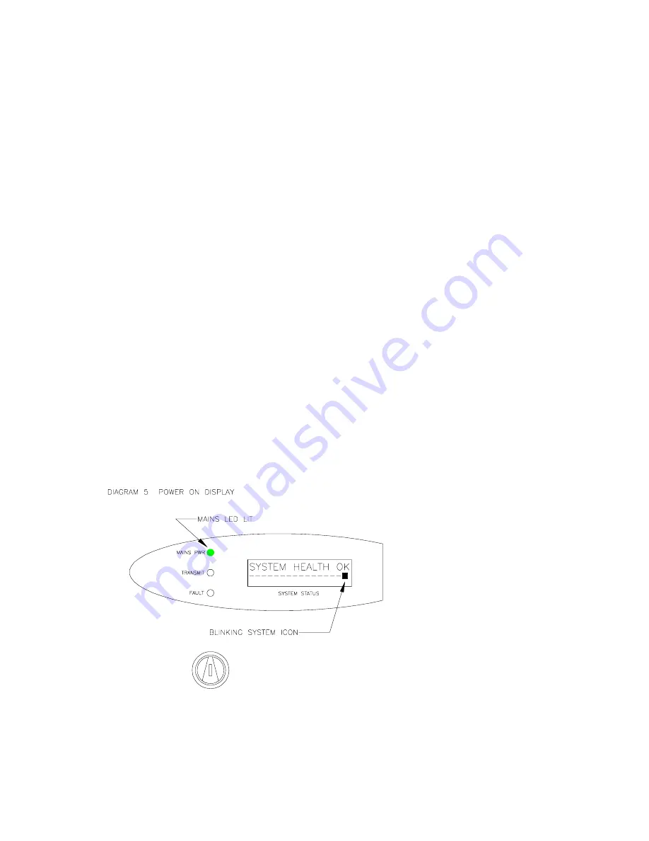
c) Now switch on the mains supply. The front panel display backlight will illuminate and the
display will state “SYSTEM HEALTH OK” on the top line. The yellow Fault LED will go out,
the sounder will stop beeping and the green Mains PWR LED will light.
d) At regular intervals (default is 50 seconds) the words “TX IN SERVICE” will briefly
appear on the bottom line of the display. At this time a test call is transmitted, which is
monitored by the pagers used on the system.
e) A system “heartbeat” indicator is provided on the bottom line right hand side of the
display, consisting of a blinking square icon. This indicates that the system’s processor is
running. In the unlikely event that the processor crashes and fails to self-recover, the icon
will “freeze” and stop blinking. An authorised technician will be required to reset the system
(see System Reset, Section 7 below).
SYSTEM TEST
RESET
ON
f)
For remote mounted antennas, it is essential at this stage to run the antenna
calibration routine to ensure accurate monitoring of the antenna’s condition
. Firstly,
check that the antenna is securely mounted in the chosen position and is clear of any
temporary obstructions (e.g. ladders, vehicles or other movable objects). Next check that
the feeder cable’s BNC connector is securely fitted to the transmitter.


