


F-Link Mk4 Supervised Transceiver System
Ref: FLNK4red
Page 9 of 23
Issue 1
2.3.5
Priority display
A zone can be set to have ‘priority display’ if required. This means that the trigger message for this zone is
displayed on top of all other messages whilst the zone is active. The display will resume cycling through other
system messages once any ‘priority’ zones have cleared. This is primarily intended for use with zones connected
to fire alarm systems. By default zone 1 is set to ‘priority display’ and zones 2-4 are set to ‘normal’.
2.3.6
Default configuration summary
MASTER: “MAIN BUILDING”
Mode
Prio
rity
NODE {X} = “BUILDING {X}”
Fol
low
M
oment
ar
y
La
tc
hed
Cl
ass C
ha
nge
Zone
Input
Type
Trigger Message
Clear Message
NO NC
1
FIRE
FIRE RESET
2
FP FAULT
FP FAULT CLEAR
3
LOCKDOWN
LOCKDOWN OVER
4
CLASS CHANGE
[blank]
If this default configuration is sufficient then the units can now be installed in their final positions around the
site. See section 3 “Installation” below for full instructions, especially section 3.1 which has important advice
about choosing suitable locations.
If a customised configuration is required then refer to page 17 which has full details of how to make
configuration changes using the supplied PC software. Only the Master needs to be reprogrammed; any
changes made are distributed wirelessly to the Nodes. Although it is still possible to make configuration
changes once the system is installed, it may be easier to carry out any necessary programming at this pre-
installation stage, before the units are installed in their final locations.
3.
Installation
3.1
Siting the hardware
Before positioning the hardware in a specific location, it is important to take into account a number of factors as
set out below:
3.1.1
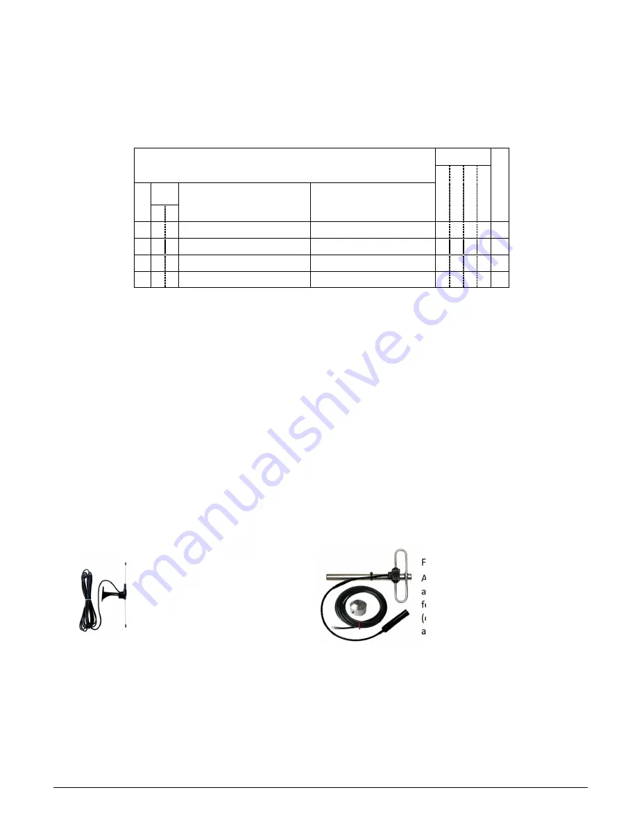
Antennas
Never operate any Scope equipment without a suitable antenna connected. The F-Link can communicate over a
considerable distance with the supplied ¼ wave antenna connected directly to the unit. On sites where difficult
operating conditions exist, it may be advantageous to install remotely mounted antenna(s):
LDPSMA
A wall-mounted mini dipole
antenna, supplied with 3m
feeder cable.
FDKIT10SMA
A heavy-duty folded dipole
antenna supplied with 10m
feeder cable and wall bracket
(optional pole mount bracket also
available).
Scope antennas are available from your usual equipment supplier.
ALWAYS use the supplied low-loss 50-ohm feed cable between the transceiver and a remote antenna. This
cable must not be coiled and can only be shortened using specialist tools and the correct RF-quality 50-ohm
connectors. Coaxial cable intended for TV, Satellite or CCTV installations is normally 75-ohm and therefore
totally unsuitable for any transmitter/receiver installation manufactured by Scope.
AVOID mounting antennas (remote or directly connected) on or close to: foil-backed plasterboard; metal mesh;
wire reinforced glass; metal sheeting; large mirrors; lift shafts; suspended ceiling grids; large metal items (e.g.
girders or steel beams); or similar. All of these can reflect, absorb or scatter radio waves and thereby reduce
the capability of the transceiver to perform its desired functions.