scope F-LINK MK4 Installation Manual Download Page 5

F-Link Mk4 Supervised Transceiver System 

Ref: FLNK4red 

Page 5 of 23


Issue 1 

2.


Pre-Installation 

We strongly recommend that steps 2.1 - 2.3 are undertaken with all units located in the same area, before 

they are installed in their final positions. 

2.1


Setting the frequency channel 
The F-Link system can operate on one of 32 frequency channels between 458.5125MHz and 458.9375MHz.  A 

full radio survey of the site should be carried out to establish the most suitable clear frequency, and a range test 

kit is available to loan from Scope.  However in the absence of a full survey it is possible to carry out a basic 

check using a single F-Link unit. 

2.1.1


Basic RSSI Check 
Working with a single F-Link unit, first connect the antenna and then connect a suitable temporary 12v or 24v dc 

power supply (or charged 12v battery) to the power input terminals.  Make sure none of the other F-Links are 

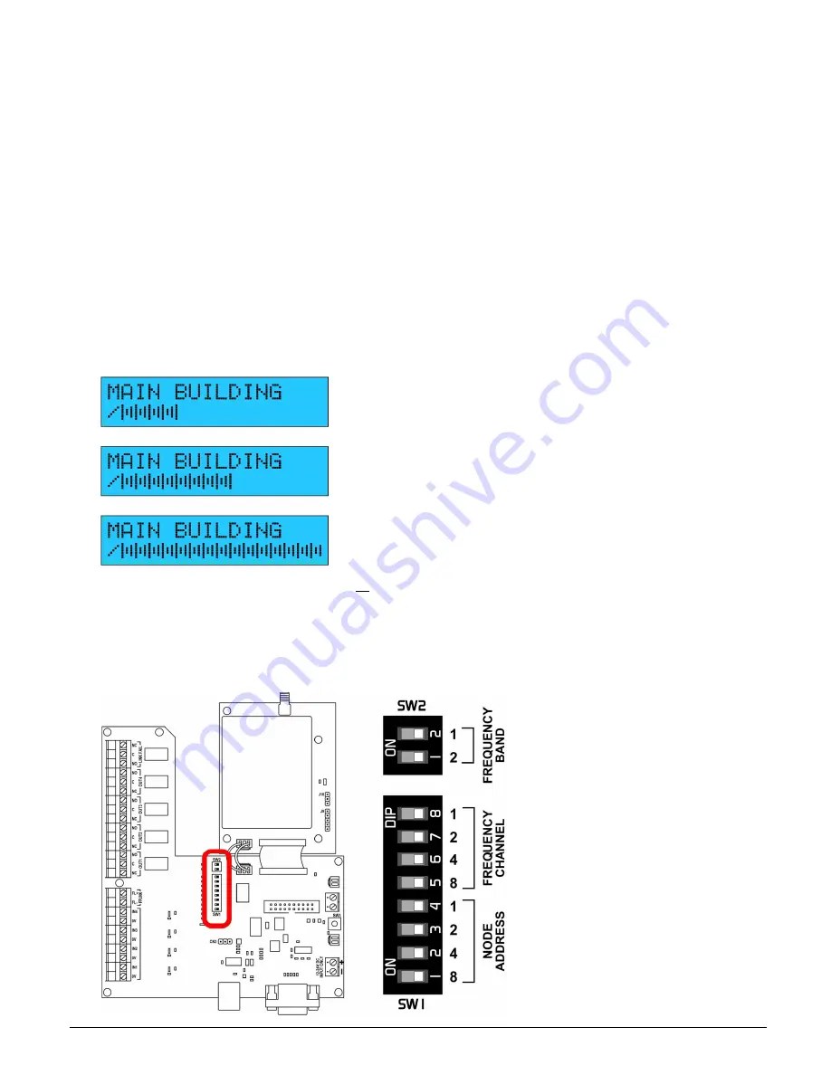
powered up.   The display will show the background RSSI signal level for the currently selected frequency 

channel as a bar graph.  A consistent level below approx. 30% suggests the chosen frequency channel is 

probably suitable for use.  If any signals are witnessed over this level then an alternative frequency channel 

should be selected, and the check repeated.  See 2.1.3 overleaf for details on how to change the frequency 

channel.   


Maximum acceptable background signal level 


Background signal level too high, try a different channel 


Strong interfering signal, try a different channel 

Once a clear frequency channel is found, set all F-Links to use this channel and proceed to step 2.2 ‘Creating the 

F-Link network’ on page 7. 

2.1.2


Dip switch settings 
The next few steps involve changing dip switch settings, which are located on the main circuit board as shown 

below.  To make changes, use a suitable non-conductive implement to carefully move each dip switch to the 

required position. 


You may need to remove a protective 

film from the top of the dip switches 

if  present  (this  is  left  over  from  the  

manufacturing process and is not 

required). 

The F-Link will detect any changes 

made to its dip switch settings and 

reboot automatically after a few 

seconds.   

If  Node  addresses  have  been 

changed then the system may also 

need to automatically redistribute its 

configuration  settings,  which  will 

take several minutes. 

Summary of Contents for F-LINK MK4

Page 1: ...ef FLNK4red Page 1 of 23 Issue 1 F LINK MK4 INSTALLATION MANUAL Scope Communications UK Ltd Quantum House Steamer Quay Rd Totnes Devon TQ9 5AL Tel 44 0 1803 860700 Fax 44 0 1803 863716 Email sales scope uk com Web www scope uk com ...

Page 2: ...roducts are designed to operate safely when installed and used according to general safety practices The following requirements should be observed at all times This equipment is designed for indoor use unless expressly stated otherwise and must not be used in classified Hazardous Areas including areas containing explosive or flammable vapours unless express authorisation has been given in writing ...

Page 3: ...hardware 9 3 1 1 Antennas 9 3 1 2 Range considerations 10 3 1 3 Environment 10 3 1 4 Mounting height 10 3 1 5 Interconnect cabling 10 3 2 Connections 10 3 2 1 Power connection 10 Zone inputs 15 3 2 2 FP link input 15 3 2 3 Reset input 15 3 2 4 Zone outputs 15 3 2 5 Link Fail output 15 3 2 6 Wiring diagrams 16 4 Configuration 17 4 1 Overview 17 4 2 General tab 17 4 3 Units tab Global 17 4 3 1 Prior...

Page 4: ...lude text descriptors for each Node and each zone event zone input type and output relay operating mode The address of each Node is set on site using dip switches as is the frequency channel used by the system An optional F Link paging transmitter can be added to the system to send alarm and fault event descriptions to portable belt worn pagers An optional interface can be fitted to provide a seri...

Page 5: ...ox 30 suggests the chosen frequency channel is probably suitable for use If any signals are witnessed over this level then an alternative frequency channel should be selected and the check repeated See 2 1 3 overleaf for details on how to change the frequency channel Maximum acceptable background signal level Background signal level too high try a different channel Strong interfering signal try a ...

Page 6: ...ct the required frequency channel The F Link will detect the change and reboot displaying the selected frequency All F Links on a system must be set to use the same frequency channel If an unavailable channel is selected e g channel 26 the F Link will automatically use the closest available channel The actual frequency in use is displayed each time the F Link reboots ...

Page 7: ... into network join mode Press and hold the join switch on the Master F Link until it displays LISTENING FOR NODES 2 Join each Node to the network Press and hold the join switch on any one Node until it displays JOINING NETWORK CONTACT MASTER Once joined it will display SUCCESSFULLY JOINED NETWORK and then reset Repeat step 2 for each Node in turn Any un joined Nodes will continue to display NOT JO...

Page 8: ... every F Link on the system By default outputs 1 3 are set as Follow and output 4 is set as Class Change Follow The output will clear when the input is cleared This is the default mode for outputs 1 3 Momentary The output will clear after a set period max 125 seconds regardless of the input state Latched The output will remain switched until manually reset using the keyswitch or external reset inp...

Page 9: ...programming at this pre installation stage before the units are installed in their final locations 3 Installation 3 1 Siting the hardware Before positioning the hardware in a specific location it is important to take into account a number of factors as set out below 3 1 1 Antennas Never operate any Scope equipment without a suitable antenna connected The F Link can communicate over a considerable ...

Page 10: ... a fire alarm system 3 1 4 Mounting height The display screen should be mounted in a location and at a height where it can be easily read by the end user Easy access to the control keyswitch on the underside of the unit will be required for reset purposes and to place the system in test mode for routine maintenance 3 1 5 Interconnect cabling A further consideration is the distance between the tran...

Page 11: ..._________________________________________________________________ Name of engineer _____________________________________________________________________________ Date of commissioning _________________________________________________________________________ Default Name Configured Name Location if different Joined Rec d Signal Master MAIN BUILDING 100 Node 1 BUILDING 1 Node 2 BUILDING 2 Node 3 BUIL...

Page 12: ...ntary Latched Class Change Priority Display 1 2 3 4 Input type Node Zone M 1 2 3 4 5 6 7 NO NC NO NC NO NC NO NC NO NC NO NC NO NC NO NC 1 2 3 4 Node Zone 8 9 10 11 12 13 14 15 NO NC NO NC NO NC NO NC NO NC NO NC NO NC NO NC 1 2 3 4 By default all inputs are Normally Open NO ...

Page 13: ...k Mk4 Supervised Transceiver System Zone messages 0 7 Zn Trigger Message Clear Message MASTER 1 2 3 4 NODE 1 1 2 3 4 NODE 2 1 2 3 4 NODE 3 1 2 3 4 NODE 4 1 2 3 4 NODE 5 1 2 3 4 NODE 6 1 2 3 4 NODE 7 1 2 3 4 ...

Page 14: ...k4 Supervised Transceiver System Zone messages 8 15 Zn Trigger Message Clear Message NODE 8 1 2 3 4 NODE 9 1 2 3 4 NODE 10 1 2 3 4 NODE 11 1 2 3 4 NODE 12 1 2 3 4 NODE 13 1 2 3 4 NODE 14 1 2 3 4 NODE 15 1 2 3 4 ...

Page 15: ...al key reset function or wired in parallel to it so the F Link can be reset either remotely or using the key See page 20 for details of the reset function This input is volt free and can be triggered by dry contact only do not apply voltage to this or any other control input 3 2 4 Zone outputs Each F Link has four zone output relays which will switch over when the corresponding input is triggered ...

Page 16: ...F Link Mk4 Supervised Transceiver System Ref FLNK4red Page 16 of 23 Issue 1 3 2 6 Wiring diagrams ...

Page 17: ...he required changes to the configuration see details below 8 Go to the File menu click Save As and save the modified configuration to your laptop or PC with a different filename 9 Click the Write button to write the modified configuration back to the Master 10 Acknowledge the success message then click DISCONNECT The Master F Link will now wirelessly distribute the changed configuration around the...

Page 18: ...g monitored by the Master Nodes which have a Network ID set but are not shown as joined are historic they have been joined at some point but are not currently part of the network or have had their node address changed 5 Network Changes The F Link network is designed to be resilient and self healing A copy of the entire system configuration is stored in every Node and can be restored by the system ...

Page 19: ...is essential 2 Power down the old Master 3 Set the frequency and address dip switches of the new Master to exactly match the old Master 4 Power up the new Master 5 Put one of the existing Nodes into Network Join Mode and join the new Master to the network see the Network Join Procedure on page 7 Note that only the new Master and one existing Node need to be joined the existing Nodes will remain co...

Page 20: ...be muted by pressing the SND MUTE button but it will re start if a new condition is detected 6 2 Status LED s POWER Unit has power ZONE A zone input or output is active FAULT ON Indicates a communication fault either local FP Link or radio Link Fail FAULT FLASH Test mode is active RESET Unit is resetting via key or remote input TRANSMIT Unit is transmitting either to update zone status or as a reg...

Page 21: ...k cannot draw enough current quickly enough when it needs to transmit then this can stop signals getting through Site attenuation signal being blocked by walls etc Conduct a radio survey to establish achievable coverage and the optimum aerial type and location Depending on the survey results relocate upgrade aerials as required see 3 1 1 on page 9 Zone stuck on not resetting Zone input still activ...

Page 22: ...d 8 17 liability 2 lid removal 4 link fail 15 21 listening for nodes 7 logging 4 maintenance 20 master address 7 name 8 replacing 19 messages 8 17 modification 4 momentary 8 17 18 mounting height 10 network 7 18 network join 7 node adding 18 address 7 deleting 18 name 8 replacing 19 noise on channel 21 normally open closed 8 15 paging 4 PC configuration 17 power supply 10 21 priority 9 17 radio su...

Page 23: ... to normally open or normally closed 1 x volt free fault input 680 end of line triggered by open or short circuit 1 x volt free remote reset input normally open Outputs 4 x configurable volt free zone output relay 1 x fault test output relay all changeover relays 50V 0 5A max Text descriptions Individual Node name 16 characters 4 x input trigger messages 16 characters each 4 x input clear messages...

Reviews: