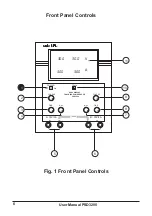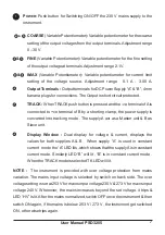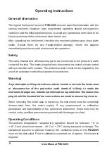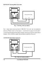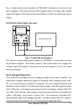
Fig. 4 shows series mode operation of PSD3205.Connections are done as per
above diagram. This mode is used to add voltage output of A supply with voltage
output of B supply. In this mode we can get maximum of 60 V, 3 A output from power
supply.
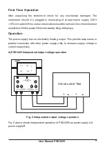
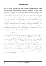
Fig. 5 above shows parallel mode operation of PSD3205. .Connections are done
as per above diagram. This mode is used to add current output of A supply with
voltage output of B supply. In this mode we can get maximum of 30 V, 6 A output
from power supply.
The instrument is provided with over voltage protection from mains variation. The
mains input voltage is selected by switch on backside. If the voltage exceeds 240 V
AC, it is recommended to select 240 V tapping. The over voltage setting for safe
operation is set at approx. 270 V for mains input voltage, when the tapping is set to
240 V. Whenever , the mains increases beyond the set voltage, it trips & LED
“
HV
”
is lit. When
“
HV
”
LED lits, switch off the instrument, & after the mains is normalized,
switch it ON again. If the mains is below 270 V, the instrument will switch ON,
otherwise trips again. If the tapping is at 230 V, & mains goes beyond 245 V approx.
Instrument will trip and shows
“
HV
”
, in such cases use tapping at 240 V.
D) PSD3205 Parallel Mode Operation
Fig. 5 Parallel Mode Operation
Over Voltage Protection
11
User Manual PSD3205
+
Circuit under Test
30.0
V
3.00
COARSE
FINE
Imax
COARSE
FINE
Imax
POWER
ON
OFF
3.00
A
V
TRACK
A: 30V/3A
B : 30V/3A
+
-
-
+
TRACK
DUAL DISPLAY
TRACKING POWER SUPPLY
PSD3204
30.0
30.0
3.00


