background image

Page 10

 INSTALLATION

RECESSING THE BENCHTOP

Benchtop thickness should be 28 - 40 mm, with a 

width of at least 600 mm. The benchtop must be 

flat and level, and the edge of the benchtop near 

the wall must be sealed to prevent ingress of water 

or other liquids.
There should be sufficient spacing around the 

opening in particular — at least 50 mm distance to 

the wall and 60 mm distance to the front edge of 

benchtop.
The distance between the edge of the opening and 

the side wall of the benchtop should be a minimum 

of 55 mm.

The benchtop must be made of materials – 

including veneer and adhesives – resistant to 

a temperature of 100°C. Otherwise the veneer 

could come off or the surface of the benchtop can 

become deformed.
The edge of the opening should be sealed with 

suitable materials to prevent ingress of water.
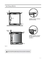
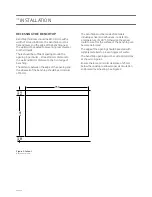
The benchtop opening must be cut to dimensions 

as shown in Figure 1.
Ensure there is a minimum clearance of 25 mm 

below the cooktop to allow proper air circulation 

and prevent overheating. See Figure 2.

750

09

4

ni

m

06

ni

m

05

Installing cooktop in kitchen 

cabinet benchtop.  

Installing cooktop in kitchen 

benchtopabove oven with 

ventilation.

5 10mm

÷

5 10mm

÷

500x10mm

25mm

30mm

500x20mm

3

2

1

Figure 1. Cutout 

Measurements in mm.

Summary of Contents for INID77

Page 1: ...INSTRUCTION MANUAL INID77 INDUCTION COOKTOP cooktop INDUCTION ceran 77cm Installation Operation Maintenance Revision V1 0 INID77 PBZ4VI527AFTB4SC...

Page 2: ...any time IMPORTANT The appliance should only be operated when you have read and understood this manual thoroughly The appliance can be only used for the purpose for which it was designed Any other us...

Page 3: ...lling the Gas Cooktop 13 Adapt the Cooktop to a Particular Type of Gas 14 Table of Burner Injector Characteristics 14 Adjust the Valves for A Reduced Flow 14 Adjust the Valves 15 Operation Turn on the...

Page 4: ...ot be performed by children without supervision Children should be supervised to ensure that they do not play with the appliance Children shall not play with the appliance Cleaning and user maintenanc...

Page 5: ...uch as knives forks spoons and lids should not be placed on the cooktop surface After use switch off the cooktop element by its controls and do not rely on the pan detector The appliance is not intend...

Page 6: ...ructions as communicated to them by persons responsible for their safety Persons with implanted devices which support vital functions eg pacemaker insulin pump or hearing aids must ensure that these d...

Page 7: ...n cooktop through damaged areas If the cooking surface is cracked switch off power to avoid the risk of electric shock DO NOT use the cooking surface as a cutting board or work table DO NOT place meta...

Page 8: ...e appliance must not be disposed of together with other household waste after it has been used The user is obliged to hand it over to waste collection centre collecting used electrical and electronic...

Page 9: ...ensor field 8 Keep Warm function sensor field 9 Child lock sensor 10 Child lock indicator light 11 Kitchen timer indicator light COOKTOP DESCRIPTION CONTROL PANEL Induction cooking zone booster rear r...

Page 10: ...the opening and the side wall of the benchtop should be a minimum of 55 mm The benchtop must be made of materials including veneer and adhesives resistant to a temperature of 100 C Otherwise the venee...

Page 11: ...n i m 0 6 Installing cooktop in kitchen cabinet benchtop Installing cooktop in kitchen benchtop above oven with ventilation 5 10mm 5 10mm 25mm 30mm 20mm 20mm 10mm 10mm Do not install the cooktop above...

Page 12: ...nto the opening and press in firmly Fig 3 CONNECTING TO ELECTRICAL MAINS Installing cooktop in kitchen cabinet benchtop Installing cooktop in kitchen 5 10mm 5 10mm 3 2 1 0mm IMPORTANT Electrical conne...

Page 13: ...type of connection and the cooktop s power rating IMPORTANT Remember to connect the Earth lead to the correct terminal block clamp marked with The electrical system supplying the cooktop must be prot...

Page 14: ...o terminal N and the protective conductor to 1N N L1 HO5VV FG 3 x 4mm2 min 30A 2 For a 230 400 V two phase connection with a neutral lead neutral lead is connected to terminal N and the protective con...

Page 15: ...mediately when the pot is placed on the cooktop and ends once it is removed Certain sounds can be heard during normal use of the induction cooktop which do not affect its correct operation Low frequen...

Page 16: ...ing automatically when a pan is detected on a cooking zone and stops heating when it is removed This helps save electricity When a suitable pan is placed on a cooking zone the display shows the heat s...

Page 17: ...tion control module and can cause overheating of the pot or pan Do not use damaged cookware such as cookware with a deformed base due to excessive heat Ensure cookware is placed on the cooking zone co...

Page 18: ...cookware Aluminium Cookware Aluminium cookware will not be detected Cast Iron Cookware High efficiency CAUTION Cast Iron Cookware can scratch the cooktop surface Enamelled Steel Cookware High efficie...

Page 19: ...et or changed If none of the sensor fields are touched within 10 seconds the appliance switches itself off SWITCH ON THE APPLIANCE To switch on the appliance touch and hold the on off sensor field 1 f...

Page 20: ...0W 260mm cooking zone from 2100W to 3400W 210mm cooking zone from 2000W to 3000W Bridge from 3600W to 5500W In order to activate the Booster function select the cooking zone and then using sensor 6 se...

Page 21: ...vates the Child Lock RESIDUAL HEAT INDICATOR Heat energy that remains accumulated in the cooking zone after cooking is called the residual heat The appliance displays two different levels of residual...

Page 22: ...tivated However you can switch on and operate individual cooking zones at any time in accordance with the operating instructions AUTOMATIC WARM UP FUNCTION Touch sensor field 3 to activate the selecte...

Page 23: ...first digit If you do not set any value for the first digit within 10 seconds the value will be set to eg The countdown starts when the Timer activation indicator light 5 starts flashing CHANGING TIME...

Page 24: ...pliance will automatically allow you to set the first digit If you do not set any value for the first digit within 10 seconds the value will be set to eg The kitchen timer starts countdown when the in...

Page 25: ...peration of all cooking zones and then resumes at the heat settings that were previously set To activate the Stop n go function In order to activate the Stop n go function at least one cooking zone mu...

Page 26: ...gar or a special cleaning agent Turn off the cooking zone before removing sugar food containing sugar plastic and aluminium foil Immediately and thoroughly scrape the leftovers off the hot cooking zon...

Page 27: ...installer Never apply a detergent on the hot cooking zone Any traces of the detergent should be wiped off clean with a damp cloth before re heating Otherwise it can be corrosive Warranty will be void...

Page 28: ...appliance does not respond and emits and extended beep Improper use wrong sensor field touched or sensors touched too briefly Reconnect the cooktop sensor fields are covered or dirty Uncover or clean...

Page 29: ...you call service as a result of operating the appliance incorrectly you will be responsible for the costs incurred even under warranty The manufacturer shall not be held liable for damage caused by f...

Page 30: ...z Rated power 7 4kW Model INID77 Induction cooking zone 220 x 190mm 210mm 260mm 210mm 260mm 2200W 2000W 2100W 2000 3000W 2100 3400W Booster induction cooking zone 220 x 190mm 210mm 260mm 2200 3700W 20...

Page 31: ...Page 31 NOTES...
Page 32: ...Schweigen Home Appliances Pty Ltd 2017 8 3 4 Anzed Court Mulgrave Victoria 3170 Phone 1300 881 693 Email sales schweigen com au www schweigen com au Schweigen Pty Ltd 2017...

Reviews: