background image

Assembly

18

04.00 | SWG | Assembly and Operating Manual | en | 389453

Ø

Check the evenness of the bolting surface, 

Mechanical

connection

 [

}

 18].

Ø

Connect the supply lines to the main air connections "A" and "B".

Connect the air connections.
OR: Mount the throttle valve to throttle and/or damp the
product sufficiently.

Ø

Connect the product with the machine/system,

Mechanical

connection

 [

}

 18] .

If necessary, use appropriate connection elements (adapter
plates).

Observe the maximal tightening torque, admissible screw-in
depth and, if necessary, strength class.

Ø

Connecting the sensor, see assembly and operating manual of
the sensor.

Ø

Assembling the sensor, 

Mounting the sensor

 [

}

 21].

Further information

2

[

}

 20]

5.2 Mechanical connection

Evenness of the
mounting surface

The values apply to the whole mounting surface to which the
product is mounted.

Requirements for evenness of the mounting surface (Dimensions in mm)

Edge length

Permissible unevenness

< 100

< 0.02

> 100

< 0.05

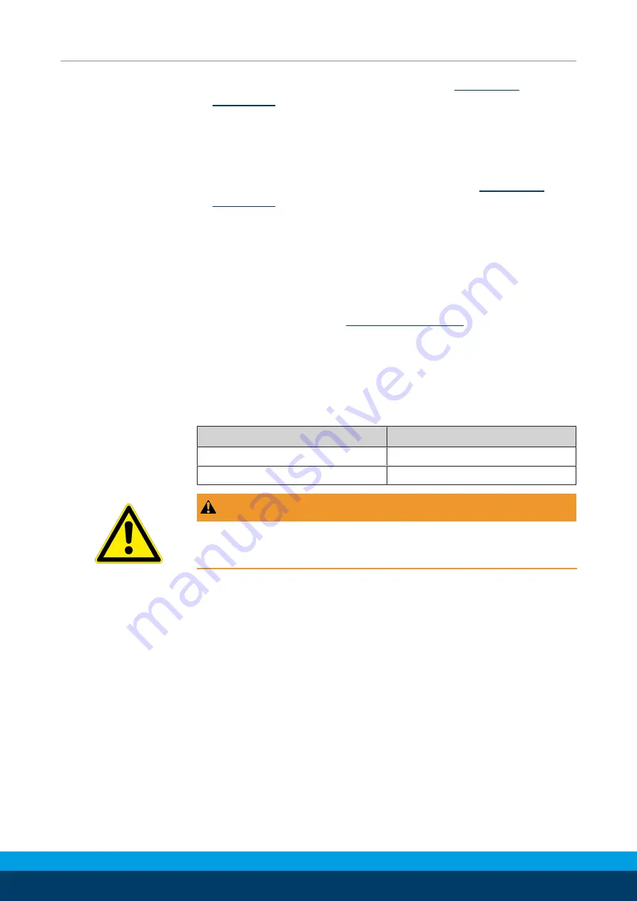
 WARNING

Risk of injury when the machine/system moves unexpectedly!

Switch off power supply.

Summary of Contents for SWG 16

Page 1: ...Translation of the original manual Assembly and Operating Manual SWG 2 Finger Angular Gripper...

Page 2: ...tions for the purpose of technical improvement Document number 389453 Version 04 00 08 08 2019 en SCHUNK GmbH Co KG All rights reserved Dear Customer thank you for trusting our products and our family...

Page 3: ...es 8 2 4 Spare parts 8 2 5 Gripper fingers 9 2 6 Environmental and operating conditions 9 2 7 Personnel qualification 9 2 8 Personal protective equipment 10 2 9 Notes on safe operation 10 2 10 Transpo...

Page 4: ...4 3 Setting dimensions 22 5 4 4 Optical proximity switch ONS 22 5 4 5 Mounting programmable magnetic switch MMS P 24 6 Troubleshooting 25 6 1 Product does not move 25 6 2 The module does not travel th...

Page 5: ...manual Illustrations in this manual are provided for basic understanding and may differ from the actual product design In addition to these instructions the documents listed under Applicable documents...

Page 6: ...3 Sizes This operating manual applies to the following sizes SWG10 SWG12 SWG16 SWG20 SWG25 SWG32 SWG40 SWG50 1 1 4 Variants This operating manual applies to the following variations SWG SWG high temp...

Page 7: ...pack 1 3 1 Accessories kit ID No of the accessory pack Accessory pack for ID number SWG 10 5516073 SWG 12 5515655 SWG 16 5513115 SWG 20 5513116 SWG 25 5513117 SWG 32 5513118 SWG 40 5513119 SWG 50 5513...

Page 8: ...r industrial and industry oriented use Appropriate use of the product includes compliance with all instructions in this manual 2 2 Not intended use It is not intended use if the product is used for ex...

Page 9: ...rious injuries and significant property damage All work may only be performed by qualified personnel Before working with the product the personnel must have read and understood the complete assembly a...

Page 10: ...handling of the personnel Incorrect handling and assembly may impair the product s safety and cause serious injuries and considerable material damage Avoid any manner of working that may interfere wit...

Page 11: ...sposal The incorrect handling of disposal may impair the product s safety and cause serious injuries as well as considerable material and environmental harm Follow local regulations on dispatching pro...

Page 12: ...d loads unattended 2 13 2 Protection during commissioning and operation Falling or violently ejected components Falling and violently ejected components can cause serious injuries and even death Take...

Page 13: ...may trigger a shock reaction leading to injuries The operator must ensure that all components and assembly groups are included in the local potential equalisation in accordance with the applicable reg...

Page 14: ...ury could occur during the base jaw procedure and when breaking or loosening the gripper fingers Wear suitable protective equipment Do not reach into the open mechanism or the movement area of the pro...

Page 15: ...012 0 25 0 4 0 85 1 6 3 8 Min pressure bar 4 0 Max pressure bar 6 5 Nominal working pressure bar 6 0 Max permissible finger length mm 10 0 12 0 15 0 18 0 22 0 28 0 35 0 42 0 Max permitted weight per...

Page 16: ...16 04 00 SWG Assembly and Operating Manual en 389453 4 Design and description 4 1 Configuration 2 Finger Angular Gripper 1 Housing 2 Main air connections 2 Base jaws 4 2 Description Narrow double acti...

Page 17: ...of inertia of the fingers is exceeded the gripper can be damaged A jaw movement always has to be without jerks and bounce You must therefore implement sufficient reduction and or damping Observe the d...

Page 18: ...ements adapter plates Observe the maximal tightening torque admissible screw in depth and if necessary strength class Connecting the sensor see assembly and operating manual of the sensor Assembling t...

Page 19: ...r fastening from below NOTE For attachment from behind or lateral fix the modular unit with the locating holes intended for this purpose Secure the modul unit with the securing holes intended for this...

Page 20: ...ir connections Item Connection SWG 10 12 SWG 16 25 SWG 32 50 1 Gripper open M2 5 M3 M5 2 Gripper closed M2 5 M3 M5 For this size the hose clips are pre assembled at the factory and the compressed air...

Page 21: ...delivery for the sensors and are available at schunk com Information on handling sensors is available at schunk com or from SCHUNK contact persons 5 4 1 Overview of sensors Designation SWG 10 12 16 20...

Page 22: ...es 16 50 the adjustment dimension applies for the following sensors Programmable magnetic switch MMS P 22 Size l1 mm Size l1 mm SWG 10 SWG 25 18 0 SWG 12 SWG 32 20 2 SWG 16 15 6 SWG 40 20 7 SWG 20 16...

Page 23: ...cal cable CAUTION Reducing the bending radius by moving back and forth causes changes in the signal incorrect switchingor rupture of the cable The minimum bending radius of the fibre optical cableis R...

Page 24: ...mal tightening torque NOTE If there is no T nut available slide the sensor according to dimension I1 into the groove 2 Setting dimensions 22 Turn the sensor 1 into the groove 2 OR Slide the sensor 1 i...

Page 25: ...t or send it to SCHUNK for repair The aperture angle is limited to 0 Check opening angle limitation 6 2 The module does not travel through the entire stroke Possible cause Corrective action Dirt depos...

Page 26: ...crews Fastening plates fixing brackets etc made of magnetisable materials If possible use aluminium or plastic 6 5 Compressed air connection is leaking Possible cause Corrective action Wrong hose Chec...

Page 27: ...SWG Assembly and Operating Manual en 389453 27 7 Maintenance The SWG Angular Gripper cannot be repaired The gripper cannot be disassembled for maintenance or repair works A damaged gripper has to be c...

Page 28: ...2 Finger Angular Gripper SWG pneumatic ID number 305104 305116 The partly completed machine may not be put into operation until conformity of the machine into which the partly completed machine is to...

Page 29: ...erall machine Fulfilled for the scope of the partly completed machine Not relevant 1 1 Essential Requirements 1 1 1 Definitions X 1 1 2 Principles of safety integration X 1 1 3 Materials and products...

Page 30: ...s of uncontrolled movements X 1 4 Required characteristics of guards and protective devices 1 4 1 General requirements X 1 4 2 Special requirements for guards X 1 4 2 1 Fixed guards X 1 4 2 2 Interloc...

Page 31: ...n from Annex 1 is to be supplemented from here forward 2 Supplementary essential health and safety requirements for certain categories of machinery X 2 1 Foodstuffs machinery and machinery for cosmeti...

Page 32: ...32 04 00 SWG Assembly and Operating Manual en 389453...

Reviews: