SCHUNK SWG 10 Assembly And Operating Manual Download Page 7

7

Montage- und Betriebsanleitung für
Winkelgreifer Type SWG

Assembly and Operating Manual for
Angular Gripper Type SWG

8.   Wartung und Pflege

8.1   Hinweise

(Pos.-Nr. siehe Kapitel 9 »Zusammenbauzeichnung«)
Beachten  Sie  unbedingt  die  Sicherheitshinweise  auf  den 
Seiten 3 und 4.
Um  die  Funktion  des  Greifers  zu  erhalten,  beachten  Sie  bitte 
folgende Hinweise:
–    Warten Sie den Greifer alle 2 Mio. Zyklen. Bei der Wartung 

sind  bestimmte  Teile  mit  Öl  bzw.  Fett  zu  montieren 
(Grundfettung).


 a)  Alle  metallischen  Gleitflächen  müssen  mit  LINO  MAX 
behandelt werden.


 b)  Die  Kolbenbohrung  sowie  alle  Dichtungen  werden  mit 
Renolit  HTL  2  oder  einem  gleichwertigen  Schmierstoff 
behandelt.

–   Bei  jeder  Wartung  des  Greifers  sind  alle  Dichtungen  zu 

erneuern (siehe Dichtsatzlisten, Kapitel 10.1). Der komplette 
Dichtsatz ist bei SCHUNK erhältlich.

–   Soweit  nicht  anders  vorgeschrieben  sind  alle  Schrauben 

und  Muttern  mit  Loctite  Nr.  243  zu  sichern  und  mit  einem 
Anzugsmoment  gemäß  DIN  anzuziehen.  (Siehe  auch  
Kapitel 8.3).

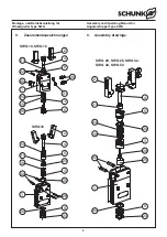
8.2   Zerlegen des Greifers

(Pos.-Nr. siehe Kapitel 9 »Zusammenbauzeichnung«)
Für SWG 10 und 12  ist das Zerlegen und ein Dichtungswechsel 
nicht vorgesehen.

Achtung!

Beachten Sie unbedingt die Sicherheitshinweise auf 
den Seiten 3 und 4.

  1.  Entfernen Sie die Druckluftleitungen.
  2.   Schieben  Sie  die  Gelenkbolzen  (Pos.  22)  –  bei  SWG  16 

zusätzlich  die  Spannstifte  (Pos.  28)  –  aus  dem  Gehäuse 
heraus.

  3.   Nehmen Sie die Finger (Pos. 2) aus dem Gehäuse (Pos. 1).
  4.   Entfernen Sie den Sicherungsring (Pos. 23).
  5.   Drehen – bei SWG 16 schieben – Sie die Führungsbuchse 

(Pos. 5) heraus.

  6.   Ziehen Sie den Deckel (Pos. 6) aus dem Gehäuse (Pos. 1) 

heraus.

  7.   Drehen  Sie  die  Schraube  (Pos.  26)  heraus  (nicht  bei  

SWG 16).

  8.   Ziehen  Sie  die  Kolbenstange  (Pos.  4)  aus  dem  Gehäuse  

(Pos. 1) heraus.

  9.   Reinigen  Sie  alle  Teile  gründlich  und  kontrollieren  Sie  alle 

Teile auf Defekt und Verschleiß.

10.  Erneuern  Sie  alle  Dichtungen  (siehe  Dichtsatzliste,  

Kapitel 10.1).

Der Zusammenbau erfolgt in umgekehrter Reihenfolge. Beachten 
Sie  dabei  die  Kapitel  8.1  und  die  Schraubenanzugsmomente 
Kapitel 8.3.

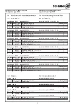
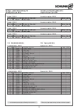
8.3   Schraubenanzugsmomente

8.   Servicing and maintenance

8.1   Notes

(For items see chapter 9, ”Assembly drawing“)
It is essential to read and observe the safety instructions on 
pages 3 and 4.
In order to ensure that the gripper continues to function properly, 
please read and observe the following instructions:
–   Service the gripper every 2 million cycles. When carrying out 

maintenance, certain parts must be oiled or greased before 
fitting (basic lubrication).


 a)  All metallic sliding surfaces must be treated with lubricant 
LINO MAX.


 b)  The piston bore and all seals must be treated with Renolit 
HLT 2 or a similar lubricant.


 The seals must be replaced each time the gripper is serviced 
(see seal kit list, chapter 10.1). The full seal kit is available 
from SCHUNK.


 Unless  otherwise  specified,  all  screws  and  nuts  must  be 
secured with Loctite No. 243 and tightened with a tightening 
torque in accordance with DIN. (See also chapter 8.3).

8.2   Disassembling the gripper

(For items see chapter 9, ”Assembly drawing“)
SWG 10 and 12 are not designed for disassembly and replacement 
of seals.

cAutIOn!

Please  read  and  observe  the  safety  instructions  on 
pages 3 and 4.

  1.  Remove the compressed air lines.
  2.   Push  the  joint  bolts  (item  22)  –  for  the  SWG  16  also  the 

clamping pins (item 28) – out of the housing.

  3.   Remove the fingers (item 2) from the housing (item 1).
  4.   Remove the circlip (item 23).
  5.   Unscrew  –  for  the  SWG  16  push  out  –  the  guide  socket  

(item 5).

  6.   Remove the lid (item 6) from the housing (item 1).
  7.   Unscrew  and  remove  the  screw  (item  26)  (not  for  the  

SWG 16).

  8.   Remove the piston rod (item 4) from the housing (item 1).
  9.   Clean all parts thoroughly and check them for any defects or 

wear and tear.

10.  Replace all the seals (see seal kit list, chapter 10.1). 

Carry out assembly in the reverse order from the above. When 
reassembling,  observe  the  instructions  in  chapter  8.1  and  the 
screw tightening torque in chapter 8.3.

8.3   Screw tightening torques

Type

SWG 20

SWG 25

SWG 32

SWG 40

SWG 50

für Schraube Pos. 26

for screw Pos. 26

0.5 Nm

0.5 Nm

1 Nm

1 Nm

4.9 Nm

Summary of Contents for SWG 10

Page 1: ...nc Tel 1 919 572 2705 Fax 1 919 572 2818 info us schunk com www us schunk com HUNGARY SCHUNK Intec Kft Tel 36 46 50900 7 Fax 36 46 50900 6 info hu schunk com www hu schunk com INDIA SCHUNK India Branch Office Tel 91 80 40538999 Fax 91 80 41277363 info in schunk com www in schunk com ITALY SCHUNK Intec S r l Tel 39 031 4951311 Fax 39 031 4951301 info it schunk com www it schunk com JAPAN SCHUNK Int...

Page 2: ...ten Technical data 5 5 Montage Assembly 5 6 Luftanschluss Air connection 6 7 Problemanalyse Trouble shooting 6 8 Wartung und Pflege Servicing and maintenance 7 8 1 Hinweise Notes 7 8 2 Zerlegen des Greifers Disassembling the gripper 7 8 3 Schraubenanzugsmomente Screw tightening torques 7 9 Zusammenbauzeichnung Assembly drawing 8 10 Dichtsatz und Ersatzteilstücklisten Seal kit and Spare part list 9...

Page 3: ...unction and or the operational safety of the gripper are to be refrained from 5 Never move any parts by hand as long as the power supply is connected 6 Never grasp into uncovered mechanisms and never grasp between the gripper fingers 1 Sicherheit 1 1 Symbolerklärung Dieses Symbol ist überall dort zu finden wo besondere Gefahren für Personen oder Beschädi gungen des Greifers möglich sind 1 2 Bestim...

Page 4: ...en AGB Diese finden Sie auf unserer Webseite www de schunk com unter Service bei den Verkaufs und Lieferbedingungen Die Einheit gilt dann als defekt wenn deren Grundfunktion Greifen oder Schwenken nicht mehr gegeben ist 7 Always disconnect the power supply lines during assembly conversion maintenance and setting work 8 Always carry out maintenance work conversions and attachments outside of the da...

Page 5: ... Top jaws 4 Technical Data see catalog The noise emitted by the gripper is 70 dB A 5 Assembly CAUTION Before starting assembly of the gripper the power supply must be switched off Please also consider the safety hints on page 3 and 4 Fastening of the SWG See Illustration 1 The centering sleeves required for centering during the fastening of the gripper and for the fixation of the gripper fingers a...

Page 6: ...rauben zur Befestigung des Greifers verwendet VA Schrauben verwenden Befestigungsplatten Haltewinkel usw aus magnetisierbaren Werkstoffen eventuell Alu oder Kunststoff verwenden CAUTION Magnetic fields and magnetisable materials can disturb the monitoring by proximity switches Only use screws made of stainless steel for fastening the grippers non magnetisable screws Fastening plates fixing bracket...

Page 7: ...er Reihenfolge Beachten Sie dabei die Kapitel 8 1 und die Schraubenanzugsmomente Kapitel 8 3 8 3 Schraubenanzugsmomente 8 Servicing and maintenance 8 1 Notes For items see chapter 9 Assembly drawing It is essential to read and observe the safety instructions on pages 3 and 4 In order to ensure that the gripper continues to function properly please read and observe the following instructions Servic...

Page 8: ...ly and Operating Manual for Angular Gripper Type SWG 9 Zusammenbauzeichnungen 9 Assembly drawings SWG 16 SWG 20 SWG 25 SWG 32 SWG 40 SWG 50 24 3 19 3 23 6 26 25 22 1 20 23 6 28 20 1 22 19 21 20 25 5 4 2 20 5 4 24 21 2 SWG 10 SWG 12 4 2 22 1 6 3 19 26 24 40 21 31 30 9 ...

Page 9: ...iption Menge Quantity 19 9610 018 Quad Ring Square ring Ø 12 42 x 1 78 1 20 9935 429 O Ring O ring Ø 19 x 1 5 2 21 9938 785 Dichtring Sealing ring Ø 8 x 11 5 x 3 2 1 Dichtsatzliste SWG 50 Ident Nr 5515 106 Seal kit list SWG 50 Id No 5515 106 Pos Item Ident Nr Id No Bezeichnung Description Menge Quantity 19 9610 001 Quad Ring Square ring Ø 5 28 x 1 78 1 20 9611 063 O Ring O ring Ø 6 x 1 2 21 9611 1...

Page 10: ... Piston rod 1 6 5516072 Deckel Cover 1 9 5516829 Ring Ring 1 19 9939723 O Ring O ring Ø 2 5 x 0 5 1 21 9611518 O Ring O ring Ø 2 x 0 5 1 22 9942283 Nadelrollen Pin rollers 1 x 4 8 2 24 9942287 Druckfeder Pressure spring 1 26 9942285 Schraube Screw DIN EN ISO 1207 8 8 M1 2 x 3 1 30 9942298 Schlauchtülle Hose nozzle M2 5 2 31 9942299 Dichtscheibe Seal Disc M2 5 2 40 9942334 Halterung Bracket 1 Pos I...

Page 11: ... 063 O Ring O ring Ø 6 x 1 2 21 9611 163 O Ring O ring Ø 4 x 1 1 22 9938 830 Nadelrollen Pin rollers 2 5 x 9 8 2 23 9907 555 Sicherungsring Securing ring DIN 472 8 x 0 8 1 24 9938 836 Druckfeder Pressure spring D 0 70 DE 5 9 LO 6 9 1 25 9937 760 Rundmagnet Circular magnet Ø 6 0 x 5 0 1 26 9660 110 Schraube Screw DIN EN ISO 4762 12 9 M2 x 6 1 30 9210 505 SMV M3 4 Schwenkverschraubung SMV M3 4 Pivot...

Page 12: ...ad Ring Square ring Ø 12 42 x 1 78 1 20 9611 061 O Ring O ring Ø 13 0 x 1 5 2 21 9938 784 Dichtring Sealing ring Ultrathan Ø 5 0 x 8 0 x 2 8 1 22 9938 772 Nadelrollen Pin rollers 4 0 x 19 8 2 23 9938 777 Sicherungsring Securing ring DIN 472 16 x 1 0 1 24 9938 839 Druckfeder Pressure spring D 1 40 DE 14 2 LO 16 4 1 25 9938 233 Rundmagnet Circular magnet Ø 10 0 x 3 0 1 26 9660 132 Schraube Screw DIN...

Page 13: ...l nen Sensoren ca 2 mA addiert 11 Accessories upon separate order If you would like more information on the operation of sensors please contact your SCHUNK representative Information is also available for download at www schunk com Products Automation Accessories 11 1 Proximity switches for SWG 16 20 25 32 40 50 Technical data Supply voltage 10 30 V DC Residual ripple 15 Max load current 200 mA sh...

Page 14: ...reifer geschlossen von Punkt 2 4 beschrieben Teil gegriffen Innengreifen 1 Spannen Sie das zu greifende Teil Gehen Sie weiter vor wie unter Greifer geöffnet von Punkt 2 5 beschrieben Gripper open 1 Set the gripper to the position Open 2 Push the solenoid switch 1 into the groove until it switches 3 Secure the solenoid switch in this position in the groove by tightening the threaded pin 4 Test the ...

Page 15: ...cal cable and align to dimension X see table and illustration Please do not use glue at the ende face of the fibre optical cable Contamination at the end face will cause incorrect signals Halterung Bracket Lichtwellenleiter in Führungsfläche der Halterung einkleben Glue in the fibre cable in the guiding area of bracket Lichtwellenleiter Fibre optic cable Lichtwellenleiter eingeklebt Fibre optic ca...

Reviews: