


9
Montage- und Betriebsanleitung für
2-Finger-Parallelgreifer Type PGH 150
Assembly and Operating Manual for
2-Finger Parallel Gripper Type PGH 150
10. Zubehör
(auf besondere Bestellung)
Benötigen Sie mehr Informationen über die Handhabung von
Sensoren, wenden Sie sich vertrauensvoll an Ihren SCHUNK-
Ansprechpartner oder nutzen Sie unsere Download-Möglich-
keiten unter
www.schunk.com>produkte>automation>Zubehör
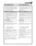
10.1 Näherungsschalter
Technische Daten:
Spannung:
10 – 30 V DC
Restwelligkeit:
≤
15%
Schaltstrom max.:
200 mA, kurzschlussfest
Schalthysterese:
≤
15% vom Nennschaltabstand
Temperaturbereich:
– 25°C bis + 70°C
Schaltfrequenz max.:
1000 Hz
Spannungsabfall ca.:
1.5 V
Schutzart nach DIN EN 60529: IP 67*
* für die Rundsteckverbindung nur im verschraubten Zustand
HiNWeis:
Die Näherungsschalter sind Zubehör und müssen gesondert
bestellt werden.
Die eingesetzten induktiven Näherungsschalter sind verpolungs-
geschützt und kurzschlussfest.
Achten Sie auf einen sachgemäßen Umgang mit den
Näherungsschaltern:
– Ziehen Sie nicht am Kabel und lassen Sie den Sensor nicht
am Kabel baumeln.
– Ziehen Sie die Befestigungsschraube oder -klemmen nicht
übermäßig fest an.
– Zulässiger Biegeradius des Kabels = 15 x Kabeldurchmesser.
– Vermeiden Sie Kontakt der Näherungsschalter zu harten
Gegenständen, sowie zu Chemikalien, insbesondere Salpeter-,
Chrom- und Schwefelsäure.
ACHTUNG:
Die induktiven Näherungsschalter sind elektro-
nische Bauteile, welche empfindlich auf hochfre-
quente Störungen oder elektromagnetische Felder
reagieren können. Prüfen Sie die Anbringung und
Installation des Kabels. Der Abstand zu hochfre-
quenten Störquellen und deren Zuleitung muss aus-
reichend sein.
Das Parallelschalten mehrerer Sensorausgänge der
gleichen Bauart (npn, pnp) ist zwar erlaubt, erhöht
aber nicht den zulässigen Laststrom. Beachten Sie
weiterhin, daß sich der Leckstrom der einzelnen
Sensoren (ca. 2 mA) addiert.
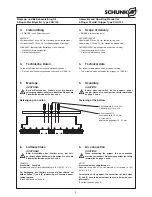
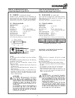
Schaltfunktion: in unbedämpftem Zustand gezeichnet
Output: drawn in non-actuated condition
10. Accessoires
(on separate order)
If you would like more information on the operation of sensors,
please contact your SCHUNK representative. Information is also
available for download at
www.schunk.com>products>automation>accessories
10.1 Proximity switches
Technical data:
Supply voltage:
10 – 30 V DC
Operation voltage:
≤
15%
Max. load current.:
200 mA, short circuit proof
Hysterisis:
≤
15% of nominal sensing distance
Range of operating temp.:
– 25°C ... + 70°C
Max operating frequency:
1000 Hz
Output transistor voltage:
approx.1.5 V
Protection class DIN EN 60529: IP 67*
* for concentric plug-and-socket connectors only in screwed-in position
Note:
Proximity switches are accessories and have to be ordered
separately.
The proximity switches used are short circuit proof and have
reverse battery protection.
Pay attention to a proper handling of the proximity switches:
– Do not pull at the cable and do not let the sensor dangle on
the cable.
– Do not overtighten fastening screws and anchoring clips.
– Admissible bending radius of the cable = 15 x cable Ø.
– Avoid the proximity switches coming into contact with hard
objects, as well as with chemicals, particularly nitric acid,
chromic acid and sulphuric acid.
CAUTioN:
Proximity switches are electronical components
which can react sensitively to high frequency inter-
ference or electromagnetic fields. Check the attach-
ment and installation of the cable. There has to be
enough distance to high frequency sources of inter-
ference and their feed lines.
Connecting several sensor outputs of the same type
(npn, pnp) in parallel is allowed, however it does not
increase the admissible load current. Furthermore
consider that the leakage current of the individual
sensors (appr. 2 mA) has to be added up.
Type
Schaltfunktion / Output
Ident-Nr. / Id.-No.
INW 80/S
Schließer / Closer
301 508
Schaltabstand / Sensing distance: 1.5 mm
braun / brown
schwarz / black
blau / blue
Last
Payload
Schließer
Closer
2 Stück / 2 pieces


