background image


_________________________________________________________________________________________ 

schunk.com 


XND.00019.003_A – 10/2018   


 32


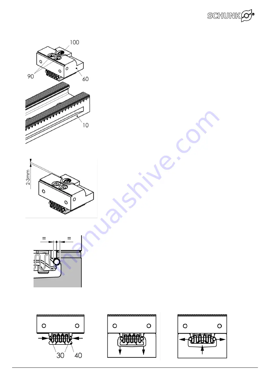
Adjustable jaws: 


4)   6)     11) 


9) 


2)    3) 

5) 

8) 


1)


It is important to ensure that the gearing of the base plate 
and jaws is clean and free from chips. 


2)


Release the two M10 fixing screws (No. 90) far enough so that 
the locking rollers with the wave springs   
(No. 30) are located in the upper indent of the clamping buckle 
(No. 40). 


3)


When the adjustable jaw (No. 60) has already been clamped, 
release the screws by approx.3 turns. This means that the 
locking rollers are in open position. 


4)


Use the clamping screw (No. 100) to open the clamping jaw far 
enough so that the upper surface of the clamping jaw projects 
by approx. 2 to 3 mm above the adjustable jaw. 


5)


Insert / extend the adjustable jaw from above into the base 
plate (No. 10). 


6)


When positioning the adjustable jaw for the respective 
workpiece size it is important to ensure that the upper face of 
the clamping jaw projects by approx. 2 to 3 mm above the 
adjustable jaw; if necessary, the clamping screw (No. 100) has 
to be opened to achieve this. 


7)


Position the adjustable jaw in the gearing to suit the clamping 
opening. 


8)


Tighten the two M10 fixing screws (No. 90); the clamping 
buckle is pulled upwards, the locking rollers are pushed 
outwards and clamped in close contact with the shape between 
the clamping buckle and the base plate. 


9)


Visually check that the locking is correct; the locking rollers 
must make full contact on both sides with the round shape of 
the base plate, which means that they are exactly half-way 
under the base plate. If there is any doubt, the locking should 
be released and the process repeated. 


10)


Tighten the M10 fixing screws (No. 90) with a torque of 50 Nm. 


11)


Use the clamping screw (No. 100) to return the clamping jaw to 
its optimum home position with the top surface of the 
clamping jaw protruding by 2 to 3 mm above the adjustable 
jaw. 


Summary of Contents for KSM2 40

Page 1: ...______________________________________ schunk com XND 00019 003_A 10 2018 1 Montage und Betriebsanleitung Installation and operating instruction Mehrfachspanner Multiple vice KSM2 H D SCHUNK GmbH Co S...

Page 2: ...8 3 1 1 Mehrfachspanner Hauptanwendung 8 3 1 2 Mehrfachspanner mit Verstellbacken H 165 9 3 1 3 Mehrfachspanner mit Keilspannelementen 10 3 1 4 Spannschiene als Basis f r Baukasten 10 4 Betrieb Norma...

Page 3: ...ezeichnet eine m gliche gef hrliche Situation Wenn die Information nicht befolgt wird k nnen Tod oder schwerste K rperverletzungen Invalidit t die Folge sein WARNUNG Bezeichnet eine m glicherweise gef...

Page 4: ...Best ckung 7 0 kg bis 30 0 kg Weitere Daten siehe aktueller Katalog Schunk station re Spanntechnik 2 2 Vern nftigerweise vorhersehbare Fehlanwendung Eine andere als die unter Bestimmungsgem sse Verwen...

Page 5: ...en welche die Funktion und Betriebssicherheit des Spannmittels beeintr chtigen sind zu unterlassen 2 3 1Backenwechsel Ungen gend angezogene Systembacken k nnen zu Besch digungen f hren Hinweise dazu f...

Page 6: ...WARNUNG Augenverletzung durch fliegende heisse Sp ne Fliegende heisse Sp ne k nnen zu schweren Augenverletzungen f hren Bei s mtlichen Arbeiten an der Maschine gelten die Vorschriften der Arbeitssich...

Page 7: ...iner Spannschiene mit obenliegender Verzahnung und einer Teilung von 2 mm Die Verzahnung ist geh rtet geschliffen und verschleissfest Auf die Spannschiene k nnen verschiedene Elemente aus dem Baukaste...

Page 8: ...nds tzlich nicht auf der Verzahnung der Spannschiene aufliegen sondern entsprechende Werkst ck Auflagen verwendet werden Die Verstellbacken werden je nach Anwendungsfall mit den geeigneten Spannbacken...

Page 9: ...tioniert und fixiert werden Dabei wird keine feste Systembacke ben tigt mindestens aber zwei Verstellbacken H 165 mm wovon eine als feste Systembacke eingesetzt wird Wie bei den normalen Verstellbacke...

Page 10: ...aft 30 kN bei einem Anzugs moment von 85 Nm 3 1 4Spannschiene als Basis f r Baukasten Die Spannschiene mit obenliegender Verzahnung kann auch als Basiselement f r die Aufnahme von weiteren Spannmittel...

Page 11: ...f7 M12 jeweils in der ersten und letzten Positionsbohrung der Spannschiene Zus tzliche Verschraubung mit normalen M12 Zylinder Schrauben durch die restlichen Befestigungsbohrungen Anziehmoment max 70...

Page 12: ...verbunden werden Die Befestigung der Spannschienen muss einzeln sichergestellt sein 4 2 Backensortiment Die zuverl ssige Funktion des Spannmittels wird massgeblich durch die richtige Backenwahl beeinf...

Page 13: ...mit einer Spannstufe H 3 mm versehen Die Spannfl che auf dieser Stufe ist mit einem Grip Profil zum Spannen von Rohteilen versehen ber die Aufnahmegewinde M8 in der Stirnfl che kann ein vielseitiges B...

Page 14: ...n bzw ausfahren 5 Die vier M10 Befestigungsschrauben kreuzweise festziehen die Klemmbride wird nach oben gezogen die Verriegelungrollen nach aussen gedr ckt und formschl ssig zwischen Klemmbride und G...

Page 15: ...sitionieren der Verstellbacke f r die entsprechende Werkst ckgr sse darauf achten dass die obere Fl che der Spannbacke ca 2 3 mm ber die Verstellbacke vorsteht gegebenenfalls durch ffnen der Spannschr...

Page 16: ...10 Spannschraube Pos 100 Empfehlung beim Spannen von mehreren Werkst cken Werkst cke mit Kugelkopf Stiftschl ssel SW8 leicht vorspannen Anschliessend alle Spannstellen mittels Drehmomentschl ssel und...

Page 17: ...iden da sonst die Spannkraft reduziert wird 6 Fehlersuche St rungsbeseitigung Spanner ist schwerg ngig Demontieren reinigen und besch digte Fl chen vorsichtig abziehen 7 Zusammenbauzeichnung Feste Sys...

Page 18: ...________________________________________________________________________ schunk com XND 00019 003_A 10 2018 18 8 Ausserbetriebnahme Das Spannmittel und alle Zubeh rteile k nnen gefahrlos als Altmetall...

Page 19: ...Multiple vice main application 25 3 1 2 Multiple vice with adjustable jaws H 165 26 3 1 3 Multiple vice with wedge clamping elements 27 3 1 4 Clamping rail as base for modular set 27 4 Operation stand...

Page 20: ...nent disability will result WARNING Indicates a potentially dangerous situation If the information is ignored it is possible that death or serious injury permanent disability will result WARNING Indic...

Page 21: ...length and tooling For further data please see the current catalogue Schunk stationary Workholding 2 2 Reasonably foreseeable misapplication Any application that is not in accordance with the Intended...

Page 22: ...nd operational safety 2 3 1Jaw change Damage may result if system jaws are insufficiently tightened For further information refer to section 4 Operation 2 3 2Notes on clamping technology The operator...

Page 23: ...ent WARNING Risk of eye injury through ejected hot fragments Ejected hot fragments can lead to serious eye injury The regulations for safety at work and the prevention of accidents always have to be o...

Page 24: ...ple clamping system is based on a clamping rail with top mounted gearing with a tooth pitch of 2 mm The gearing is hardened ground and wear resistant Several elements from the modular system can be pl...

Page 25: ...be placed on the gearing of the clamping rail instead appropriate workpiece supports should be used The adjustable jaws are fitted with suitable clamping jaws to suit the application Pull down jaw gr...

Page 26: ...normal adjustable jaws In this case no fixed jaw is needed but at least two H 165 mm adjustable jaws are necessary with one of them being used as a fixed jaw The H 165 mm adjustable jaws are fitted wi...

Page 27: ...screw with SW 8 hexagon socket The max clamping force is 30 kN at a torque of 85 Nm 3 1 4Clamping rail as base for modular set The clamping rail with top mounted gearing can also be used as a base el...

Page 28: ...one each in the first and last positioning holes of the clamping rail Additional fixing is possible with normal M12 cylinder screws in the other fixing holes Torque max 70 Nm 4 1 3On VERO S zero poin...

Page 29: ...ing of the clamping rails has to be individually ascertained 4 2 Jaw range The reliability of the clamping device function depends significantly on the correct selection of jaws 4 2 1Adjustable jaws a...

Page 30: ...amping step of H 3 mm The clamping area on this step has a grip profile for clamping un machined parts A multi sided jaw configuration can be adapted using the M8 female threads in the face of the uni...

Page 31: ...5 Tighten the four M10 fixing screws crosswise the clamping buckle is pulled upwards the locking rollers are pushed outwards and clamped in close contact with the shape between the clamping buckle and...

Page 32: ...justable jaw for the respective workpiece size it is important to ensure that the upper face of the clamping jaw projects by approx 2 to 3 mm above the adjustable jaw if necessary the clamping screw N...

Page 33: ...M10 clamping screw No 100 Recommendation for clamping several workpieces Slightly pre tension the workpieces with an SW8 ball end hexagonal key Proceed to clamp all clamping points using the torque w...

Page 34: ...should be avoided as this will reduce the clamping force 6 Troubleshooting eliminating faults Vice is hard to operate Dismantle clean and damaged surfaces must be carefully levelled off with a honing...

Page 35: ...____________________________________________________________________ schunk com XND 00019 003_A 10 2018 35 8 Taking out of service The clamping device and all accessories can be disposed of as scrap m...

Page 36: ...______________________________________________________ schunk com XND 00019 003_A 10 2018 36 H D Schunk GmbH Co Spanntechnik KG Lothringer Strasse 23 D 88512 Mengen Tel 49 7572 7614 0 Fax 49 7572 7614...

Reviews: