Assembly and settings
02.02|AGE-F-XY 31-80|en
13
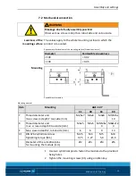
Mechanical connection
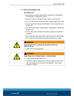
WARNING
Breakage due to faulty assembly possible!
Observe max. screw-in depth on robot-side and on tool-side.
The values apply to the whole mounting surface to which the
product is mounted .
Requirements for levelness of the mounting surface (Dimensions in mm)
Diameter
Permissible unevenness
< 100
< 0.02
> 100
< 0.05
Possibilities of assembly
Mounting material
Item
Mounting
AGE-F-XY
31
40
63
80
Y
Thread diameter and
max. screw-in depth Y tool-side [mm]
M2,5x7 M3x8
M4x8 M5/M6x
10
X
Thread diameter and
max. screw-in depth X tool-side [mm]
M3x5 M3x5 M5/M6x
9
M8x12/2
0
Z
Max. srew-in depth Z, robot-side [mm]
6
6
9
13
31
DIN 4762 cylindrical screw
Tightening torque [Nm]
M2,5
0,75
M3
1,27
M5
5,9
M8
24,6
Diameter of the cylindrical pins
for mounting the module [mm]
Ø2
Ø3
Ø4
Ø6
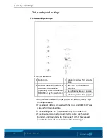
1 Use two cylindrical pins to fasten the module via the provided
fixing holes.
2 Tighten the mounting screws (31) using an Allen key.
7.2
Levelness of the
mounting surface
Mounting


