


SHEET 04/04
025.0281-0
05/2009
rev. 09
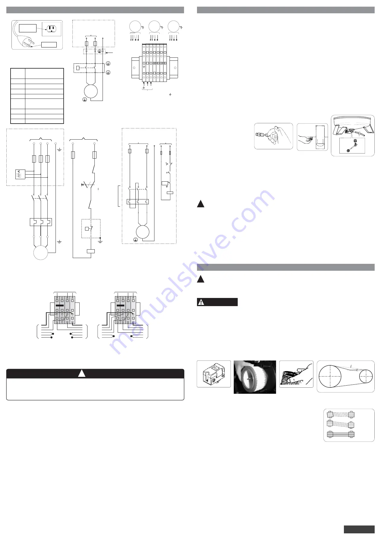
7) INSTALLATION
7) INSTALLATION
4.9
.
For your safety, an on/off switch must be installed (before the fuse box) to switch off electric power during
maintenance or equipment adjustments (must be according to current of electric motor, Table 2)
4.8 Box connections compressor MSV 12/175
GROUND
PLUG 2P+GR
P
F1
Main supply
M
1~
Phase
N
Neutral
FIGURE 7 -
ELECTRIC DIAGRAM
(MOTOR WITH
THERMAL PROTECTOR)
Owner’s responsibility
F1
F2
P
M
FT1
KSFF
K1
SH1/CH
XS
Fuse type "D" or "NH"
(see Table 2)
Command fuse 2A
Pressure switch
Electric motor
Overload relay
Sequence and phase
fault relay
Contactor
ON/OFF switch
Connector
FIGURE 9 - THREE-PHASE
MOTOR - DIRECT START
R
T
S
3~
MOTOR
2
U
FT1
1
K1
2
1
KFSF
4
6
W
V
PE
5
3
6
4
5
3
Main supply
Owner’s responsibility
F1
R
GR
S
PE
K1
SH1
KSFF
I
F21
L1
Comand Voltage
P
A1
A2
FT1
95
96
16
15
0
I
0
F21
L2
FIGURE 10 - ELECTRIC DIAGRAM
SINGLE-PHASE
K1
FT1
1
1
2
2
3
3
4
4
5
5
6
6
Supply voltage
Owner’s responsibility
M
1~
F1
GROUND
Comand
Voltage
F21
FT1
96
95
CH
K1
A1
A2
P
For maintenance in warranty, the electrical installations or to change the voltage of the machine, it must
be realized by a technical specialized electrical that must follow the diagrams of this manual. The
expenses are responsibility of the owner/client, if you have any doubt, a Schulz Authorized
Technical/Distributor must be consulted.
ATTENTION
!
FIGURE 11 - ELECTRICAL DIAGRAM WITH BOX CONNECTIONS
(CHANGE OF VOLTAGE)
220 V
Pressure Switch
1
1
1
1
3
3
3
3
4
4
4
4
4
3
1
7
2
4
1
3
2
7
1
3
4
7
2
1
4
3
2
7
GROUND
GROUND
GROUND
GROUND
GROUND
GROUND
M1
M1
M2
M2
110 V
Assembly
(according to Table 2)
FIGURE 8 – ELECTRIC DIAGRAM
IN 220V - MSV 18/250
MAIN SUPPLY:
LINE (L) , NEUTRAL (N) AND GROUND
M3.1
M3.4
M2.1 M1.4 M2.4
M1.1
M 1
M 2
M 3
7
3 2
1 4
7
3 2
1 4
7
3 2
1 4
L
N
01
02
03
04
05
06
Assembly (according to Table 2)
5. Cabinet installation procedure:
5.1
5.2
5.3
5.4
5.5
16
5.6
Before connecting the cabinet to the electric supply, check if the indicated voltage in the input wire tag is the
same as the voltage indicated in the compressor.
Lift the cabinet.
Place it over the compressor.
Lower it toward the compressor until it touches the floor. Check that the rear lid of the electric motor
perfectly fits the left side hole inside the cabinet.
Connect the compressor wire
or the plug inside the cabinet.
To energize the set (c compressor), connect input cabinet wire to the electric supply.
Note:
1- Models MSV 12/175 and MSV 18/250 are factory supplied with electric wire without the plug.
2- Select the plug or the electric connection device according to the electrical parameters of the product,
see Table 2.
3- The energy supply network must not present voltage changes over ± 10%.
4- The voltage drop caused by the motor start must not be over 10%.
5- The compressor acoustic cabinet, with vertical receiver volume of 30 liters, is factory supplied with
115 or 230 (V) electric connection. If you need to change the voltage, check the diagram placed inside
the cabinet, which will guide you to change the voltage.
6- The thermal protector 19 is located inside the electric motor for models MS 3, MSV 6, CSA 6,5, MSV 12
and MSV 18. If it goes off, it will re-start the compressor after the temperature drops. The installation of
protection fuses is necessary, see Table 2.
7- Used start key and fuse kind delayed-action.
- INSTALLATION EXPENSES ARE OF PURCHASER'S RESPONSIBILITY.
8) START PROCEDURE
8) START PROCEDURE
FIRST START PROCEDURES
1.
2.
Turn be start key (assembly by customer for compressor without key) and check if the rotation direction is anti-
clokwise, viewed from the fan.
4.
5.
6.
7.
8.
Check if the internal fan inside the acoustic cabinet continues turned on after the compressor shuts off at 8.3
bar. It must be on, in order to maintain the internal temperature equal to the environment temperature.
After the arrangements regarding location, the pressure vessel adequacy to local Technical Norms and
Legislations, the installation of the electric network and the compressed air network are made (customer's
responsibility), do the following:
10
3.
Important:
6
Completely open the pressure regulator
or air control valve.
Let the compressor run for about 10 (ten) minutes to allow a homogeneous lubrication of the moving parts.
Totally close the pressure regulator or air control valve, so that the compressor can fill up the tank. The
compressor will automatically turn off (through the pressure switch, Figure 15) when the pressure gauge shows
maximum pressure around 120 psig (8.3 bar).
Open the pressure regulator or air control valve to release the compressed air from the tank, to decrease its
internal pressure. The compressor will automatically re-start (through pressure switch) when the pressure
gauge shows pressure around 80 psig (5.5 bar).
Check the air tank’s filling up time according to Table 1.
Close the pressure regulator and unplug the equipment.
Verify if safety valve (Figure 12) is working.
FIGURE 12
FIGURE 13
FIGURE 14
Note:
17.
After the job finished,
the compressor’s tank
pressure is between 5.5 and
8.3 bar. Switch off the drive
button on the cabinet
It
will help to save electric
power.
9.
Open the drain petcock to exhaust the condensed water inside the tank and close it right after (Figures 13 and
14).
Open the regulator or air control valve to completely exhaust the tank and close it right after.
Your Schulz compressor is ready to operate. Connect it to the air distribution network and start the electric
motor. When the compressor reaches maximum pressure, open the pressure regulator so that the air can flow
into the distribution network. Check if there is any leakage along the tubing, by using water and soap lather. In
case there is any, eliminate it.
8
10.
11.
ATTENTION:
A compressor with good dimensions will have roughly six (6) starts per hour 70% ON and
30% OFF/unload.
!
Note:
-
-
1
2
10
3-
Important:
Attention:
The initial start procedure must be repeated whenever maintenance occurs or when the compressor is moved
to another place.
The pressure regulator
must be used as follows: Pull knob turning right or left to set desired pressure, push
knob down. The desired work pressure will be shown in the regulator sight.
For your comfort, Schulz manufacturer of the product compressor provides an electronic drain, model PS 16,
which is adaptable to the tank exhaust connection (drain) and that can be purchased at Schulz Authorized
Technical/Distributor.
When installing it, the tank must be depressurized (empty).
See item 9 of Chapter 5 - Safety Instruction.
9) PREVENTIVE MAINTENANCE
9) PREVENTIVE MAINTENANCE
!
In order to guarantee the perfect compressor operation and to extend its lifetime, follow the
recommendations below:
1. Daily
Check abnormal noise or vibration in the compressor. If the problem persists after the following corrective
actions had been taken, get in touch with the nearest Schulz Authorized Technical/Distributor.
Inspect
Check if the belt, located inside the belt protector
A.
B.
2. Weekly
A.
B.
C.
D.
3.
Montly
A.
Drain the condensed water from the tank, through petcock (Figures 13 and 14).
Clean the external parts of the compressor with neutral detergent or with a wet cloth.
Verify the operation of the safety valve (Figure 12).
the intake filter
, (Figure 5 and 16 for models CSV 15 and CSV 20) or when supply in special
condition (Figure 17) when the filter element clogged is necessary change.
, (CSV 15 and CSV 20), is making abnormal noise or
movements. If so, see item (4C) procedure below.
Check the operation of the pressure switch (Figure 15) (see items 4 and 5 the Chapter 8 - Start Procedure).
8
6
12
20
ATTENTION
RISK OF PERSONAL INJURIES
The maximum pressure of the tank when drained must be 10 psig (0.7 bar).
FIGURE 15
FIGURE 17
FIGURE 16
FIGURE 18
x = belt deflection
weight/strength
x
FIGURE 19
CORRECT
INCORRECT
INCORRECT
4. Quarterly
A.
B.
C.
Change the intake filter element every 300 (three hundred ) hours or
quarterly (whichever occurs first).
Tighten pump unit bolts (see Table 4) with a torquemeter and nuts with
manual tools. For model CSA 6.5/30 check if compressor makes
abnormal noise in the inner part of the case.
Verify the tension of the belt (Figure 18) and the alignment (Figure 19)
for models CSV 15 and CSV 20. The tension at the middle point yields
3/8” through 1/2” on manual force being or weight of 4,0 kg (1,8 lbs)
applied at the mid-point. In order the check the deflection, remove the
belt cover. After the inspection reassemble the protector, fixing the
screws as per Table 4.
Inspect the intake crankcase filter
, when the filter clogged clean it using a maximum pressure of 2,0 bar
(30 psig) or change when damaged.
Lubricate connecting rod(s) upper bearing, with Barrierta L55/2 (Klüber) for models MS 3, MSV 6, MSV 12
and MSV 18.
Lubricate connecting rod(s) upper bearing, with Barrierta L55/2 (Kluber) for models CSV 15 and CSV 20.
Inspect and clean the valves (located between the cylinder's upper part and its head).
Replace connecting rod(s) lower bearing for models MS 3, MSV 6, CSA 6.5, MSV 12 and MSV 18.
Replace rings on the piston [if the filling up time is 20% higher than what is specificated in Table 1]
Inspect and clean the check valve * .
*
See item 9, Chapter 5 - Safety Instruction.
Have the pressure switch, pressure gauge and safety valve, according to local technical norms. This
operation must be carried in a device not attached to the air tank.
D.
24
5. Every six months
A.
6. Every 1,000 hours or 9 months (whichever occurs first)
A.
B.
C.
D.
E.
7
Attention:
7. Yearly
A.
OUTLET WITH
GROUNDING
CONNECTION
GROUNDING
PIN
FIGURE 6 - FOR MODELS
MSV3, MSV 6 AND CSA 6,5
*
* Obs.: The kit K1 + FT1 can be two poles
depends on product version.


