


© 2016 Alamo Group Inc.
SRW1400
Published 08/16
S/N
:
R20011130602-R20011
314712
Inclusive
P
art No. R200-010C
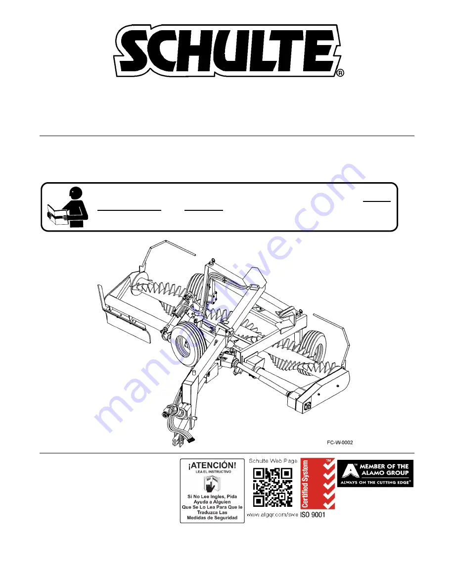
OPERATOR’S MANUAL
Schulte Industries Ltd.
PO Box 70
Englefeld Saskatchewan
Canada S0K 1N0
Tel. (306) 287-3715
Fax. (306) 287-3355
Parts Fax. (306) 287-4066
Web: www.schulte.ca
PIVOTING ROCK WINDROWER
This Operator's Manual is an integral part of the safe operation of this
machine and must be maintained with the unit at all times. READ,
UNDERSTAND, and FOLLOW the Safety and Operation Instructions
contained in this manual before operating the equipment.
C01-Cover
Summary of Contents for SRW1400
Page 4: ......
Page 7: ...Safety Section 1 1 2016 Alamo Group Inc SAFETY SECTION ...
Page 21: ...SAFETY SRW1400 08 16 Safety Section 1 15 2016 Alamo Group Inc SAFETY Decal Description ...
Page 22: ...SAFETY SRW1400 08 16 Safety Section 1 16 2016 Alamo Group Inc SAFETY ...
Page 23: ...SAFETY SRW1400 08 16 Safety Section 1 17 2016 Alamo Group Inc SAFETY ...
Page 24: ...SAFETY SRW1400 08 16 Safety Section 1 18 2016 Alamo Group Inc SAFETY ...
Page 26: ......
Page 27: ...Introduction Section 2 1 2016 Alamo Group Inc INTRODUCTION SECTION ...
Page 30: ......
Page 31: ...Assembly Section 3 1 2016 Alamo Group Inc ASSEMBLY SECTION ...
Page 38: ......
Page 39: ...Operation Section 4 1 2016 Alamo Group Inc OPERATION SECTION ...
Page 79: ...Maintenance Section 5 1 2016 Alamo Group Inc MAINTENANCE SECTION ...