52
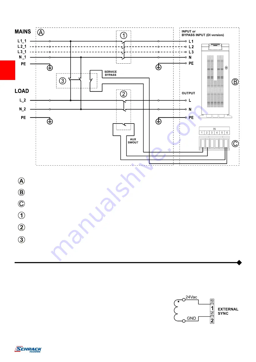
DIAGRAM SHOWING REMOTE INSTALLATION OF THE MAINTENANCE BYPASS (USS3M MODEL)
Main switchboard
Internal connections of the UPS
Programmable IN/OUT port (to be configured via the configuration software)
INPUT switch: for correct sizing refer to the "Internal Protective Devices” paragraph
OUTPUT switch: for correct sizing refer to the "Internal Protective Devices” paragraph, equipped with a normally closed
auxiliary contact
SERVICE
BYPASS switch: for correct sizing refer to the "Internal Protective Devices” paragraph, equipped with a normally
closed auxiliary contact
E
XTERNAL
S
YNC KIT
In order to synchronise the inverter output to an external source, a synchronisation kit
is available. This kit contains an isolated single-phase low voltage output transformer
(SELV).
Connect the transformer secondary to the "EXT SYNC" terminal block (marked as 1
and 2) in the power connections area (refer to the “Power connection details” paragraph
of the Installation manual for further information) using a double insulated cable with a
1mmsq cross-section.
Make sure the polarity is respected as shown in the figure.
After installation, enable the control using the configuration software.
For EMI issues, keep the cable length as short as possible (suggested 25 mt maximum).
If extended length is required, please contact your local service centre.


