


5
SLG 420
Operating instructions
Safety light grid
EN
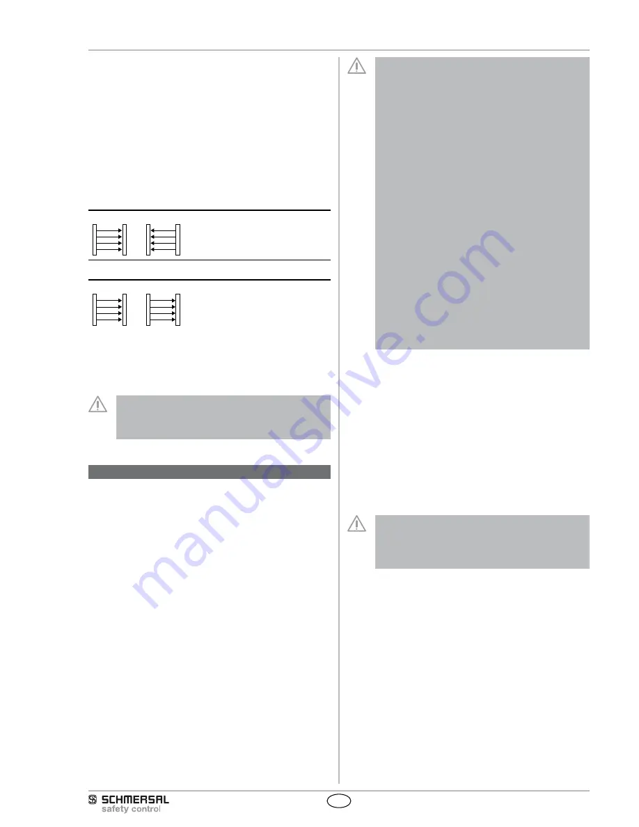
2.10 Beam coding
The beam coding of the safety light grid must be adjusted, when
systems operating in each other's vicinity and a set-up as shown in the
image below (no interference) is impossible.When supplied, the beam
coding is not active. With beam coding A, a receiver can distinguish the
beams of the transmitter with the same beam coding, which are desti-
ned to this particular receiver, from foreign beams. The beam coding A
must be set for each sensor (receiver and transmitter) individually. The
function is activated by means of the NSR-0801 BUS converter and a
PC or laptop.
If adjacent systems are operated without beam coding, the user is at
risk.
no interference
E
E
R
R
Interference: beam coding required!
E
R
R
E
• The beam coding increases the safety and avoids mutual interference
of adjacent systems.
• The beam coding increases the immunity against optical interference
(e.g. sun light, welding sparks).
• The beam coding A is permanently shown by the transmitter and the
receiver by means of flashing LED's (refer to LED status information).
The response time of the system is increased when beam
coding A is used. To this end, the safety distance must be
adjusted to the hazardous movement. Refer to chapter
Response time.
3. Mounting
3.1 General conditions
The following guidelines are provided as a preventative warning notice
to ensure safe and appropriate handling. These guidelines are an
essential part of the safety instructions and therefore must always be
observed and respected.
• The SLG 420 must not be used on machines, which can be
stopped electrically in case of emergency.
• The safety distance between the SLG 420 and a hazar-
dous machine movement must always be observed and
respected.
• Additional mechanical safety guards must be installed so
that the operator has to pass by the protection field to reach
the hazardous machine parts.
• The SLG 420 must be installed so that the personnel always
must be outside of the hazardous area when operating the
machine.
• An incorrect installation can lead to serious injuries. An
incorrect installation can lead to non-detected areas.
• Never connect the outputs to +24VDC. If the outputs are
wired to +24VDC, they are in ON state, as a result of which
they are unable to stop a hazardous situation occuring on
the application/machine.
• The safety inspections must be conducted regularly. The
SLG 420 must not be exposed to inflammable or explosive
gasses.
• The connecting cables must be connected in accordance
with the installation instructions. The fixing screws of the
end caps and the mounting angle must be firmly tightened.
• Additional measures could be required to ensure that the
electro-sensitive device does not present a dangerous
breakdown, when other forms of light beams are available in
a special application (e.g. use of wireless control devices on
cranes, radiation of welding sparks or effects of strobosco-
pic lights).
3.2 Protection field and approach
The protection field of the SLG 420 consists only of the available
individual beams with a distance of 300, 400 or 500 mm. Additional
protective devices must ensure that hazardous machine movements
can only be reached after passing through the protection field.
The SLG 420 must be installed to so that the hazardous area is com-
pletely protected, if necessary by means of additional safety guards.
The safety distance before the hazardous point to the SLG safety
guard must be imperatively respected. The safety distance enables the
presence of persons within the hazardous area. Therefore, it must be
ensured that the hazardous movement can only take place, when no
persons are inside the hazardous area anymore.
The legal and governmental provisions must be observed for the
operation and use. These provisions are usually region- and country-
dependent.
The command devices (enabling button) must be installed
outside of the hazardous area sot hat any operation from
within the hazardous area is prevented. The operator must
have a clear view on the hazardous area, when actuating the
command device (enabling button).
3.3 Alignment
Procedure:
1. The transmitter and the receiver must be fitted parallel to each other
and at the same height.
2. Turn the transmitter and monitor the diagnostic window of the recei-
ver. Fix the light grid, when the LED OSSD ON (green) is on and the
LED signal reception (orange) is off.
3. Determine the max. rotating angle to the left and to the right, at which
the LED OSSD ON (green) is on and tighten the mounting screws in
central position. Make sure that the LED signal reception (orange) is
not on or flashing.