


3
BNS 260 AS
Operating instructions
Safety sensor
EN
3. Mounting
3.1 General mounting instructions
Please observe the remarks of the standards ISO 12100,
ISO 14119 and ISO 14120.
• Fitting is only authorised in a de-energised condition
• Do not use the sensor and the actuator as a mechanical backstop.
• Any mounting position, provided that the active surfaces are opposite
• Do not subject the safety sensor and actuator to extreme vibrations
and shocks.
To avoid any interference inherent to this kind of system and any
reduction of the switching distances, please observe the following
guidelines:
• Ensure the safety sensor is mounted on a flat surface
• Do not install the safety sensor and the actuator in strong magnetic
fields
• If possible, do not mount the sensor and the actuator on ferromagnetic
material. A non-magnetic spacer of at least 5 mm thick or the original
spacer must be used. The use of non-magnetic fixing screws is
recommended also.
• Keep away from metal chips
• The mounting distance between two sensors should always be at
least 50 mm
The actuator must be permanently fitted to the safety guards
and protected against displacement by suitable measures
(tamperproof screws, gluing, drilling of the screw heads).
3.2 Dimensions
All measurements in mm.
Sensor with cable, for left hinged door
26
6
2000
13
36
4
19
22
¤ 4,5
LED
BPS 260-1/-2 actuator
6
13
36
26
4,5
4
19
22
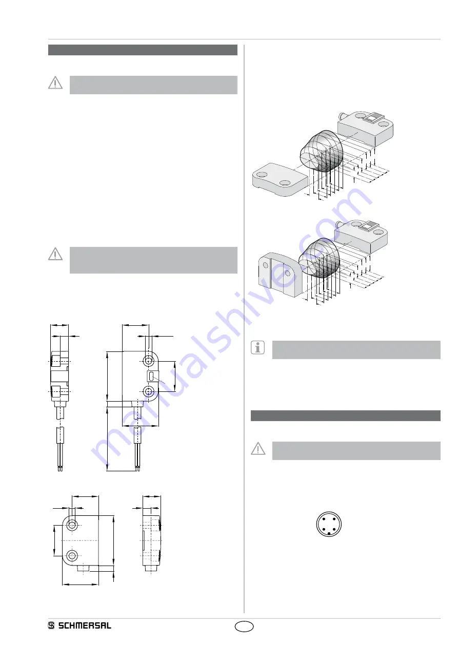
3.3 Axial misalignment
A horizontal and vertical misalignment of the safety sensor and the
actuator is tolerated. The possible misalignment depends on the
distance of the active surface of the sensor and the actuator. The
sensor remains active within the tolerance range.
The specified switching distances refer to opposedly mounted safety
sensors and actuators.
3,5
3,5
3,5
3,5
3,5
3
3
4
5
2 1
0
5
5
5
4
3
2
BPS 260-1
3,5
3,5
3,5
3,5
3,5
3
3
4
5
2 1
0
5
5
5
4
3
2
BPS 260-2
Assured switching distance: s
ao
= 5 mm
assured switch-off distance: sar = 15 mm
Recommended Adjustment
Align the safety sensor and actuator at a distance of 0.5 x s
ao
.
3.4 Adjustment
Adjust the safety sensor and the actuator to the safety guard. The
correct functionality of both safety channels must be checked by means
of the connected safety-monitoring module.
4. Electrical connection
4.1 General information for electrical connection
The electrical connection may only be carried out by
authorised personnel in a de-energised condition.
Connection to the AS interface system is realised through the vacant
cable end or an M12 connector. The M12 connector is A-coded.
The wiring configuration of the M12 connector is defined as follows (to
EN 62026-2):
spare
3
2
1
4
AS-Interface - (blue)
AS-Int (brown)
spare