2
Operating instructions
Locking rod
AZ/AZM 200-B30-P30/-P31
AZ/AZM 201-B30-P30/-P31
EN
2. Product description
2.1 Ordering code
This operating instructions manual applies to the following types:
AZ/AZM 200-B30-
➀
TA
➁➂
-
➃
AZ/AZM201-B30-
➀
TA
➁➂
-
➃
No. Option
Description
➀
L
Door hinge on left-hand side
R
Door hinge on right-hand side
➁
G1
with doorhandle
G2
with rotating knob
➂
P30
Locking rod without emergency exit
P31
Locking rod with emergency exit
➃
without lockout tag
SZ
with lockout tag
Only if the information described in this operating instructions
manual are realised correctly, the safety function and
therefore the compliance of the entire system with the
Machinery Directive is maintained.
2.2 Special versions
For special versions, which are not listed in the order code below 2.1,
these specifications apply accordingly, provided that they correspond to
the standard version.
2.3 Destination and use
The actuator unit with emergency exit release is used to open the
safety guard inside the hazardous area. By actuating the emergency
exit, the safety guard can be opened from within the hazardous area
without the need for unlocking the solenoid interlock. The safety guard
cannot be locked from inside. Particularly suitable for double wing doors
as a system with higher mechanical stability that also offers protection
in the event of larger workpieces being thrown out.
Fitting and actuation of emergency exit release only
from within the hazardous area.
3. Mounting
3.1 General mounting instructions
The installation may only be carried out by authorised
personnel.
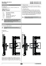
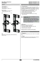
3.2 Dimensions
All measurements in mm.
P30
P31
190
75
8,5
65
65
150
23
40
44
13,8
83
13,8
190
75
8,5
65
65
150
23
40
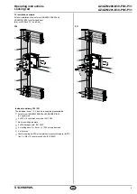
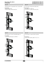
Assembly of the system AZ/AZM 200 and AZ/AZM201 with actuators
AZ/AZM 200-B30 and AZ/AZM201-B30 is performed following the same
work steps as those described in the relevant operating instructions.
Worksteps that differ or supplement these are to be observed as follows.
Summary of Contents for AZ/AZM 201-B30-P31
Page 7: ......

