7
AST LC ST-AS
Operating instructions
Opto-Tube
EN
4. Rear side Electrical connection
4.1 General information for electrical connection
The electrical connection to the AS-i system may only be
carried out by authorised personnel in a de-energised
condition (refer to EN 50295).
Connection to the AS-Interface system
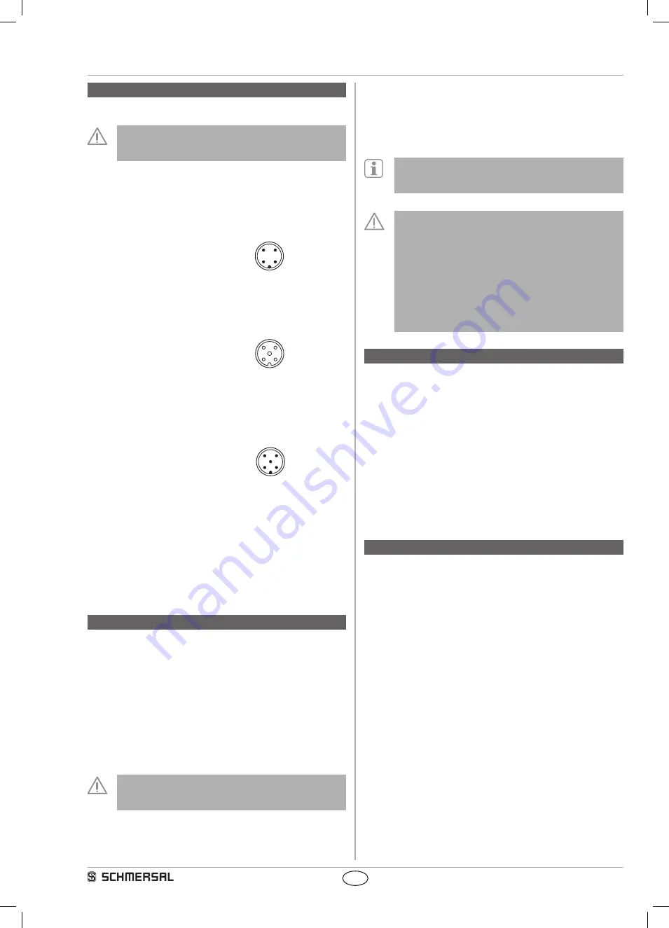
The connection to the AS-Interface system is realised through an M12
connector (ST). The following wiring configuration is applicable for the
AS-i Slave (cable configuration to EN 50295):
ST
1:
AS-i +
3
2
1
4
2:
spare
3:
AS-i -
4:
spare
Connection of the light grid (receiver)
The connection to the light grid (E) is realised through an M12
connector (ST2). The wiring configuration is as follows:
ST2
1:
+ 24 VDC
3
2
5
1
4
2:
OSSD 1
3:
GND
4:
OSSD 2
5:
FE (functional earth connection)
Connection of the 24V voltage supply of the light grid
The 24V voltage supply (PELV unit to IEC 364-4-41) is connected
through an M12 connector (ST1). The wiring configuration is as follows:
ST1
1:
+ 24 VDC
3
2
5
1
4
2:
spare
3:
GND
4:
spare
5:
FE (functional earth connection)
For the installation of the Opto-Tube and a light grid, the following
boundary conditions must be observed:
- the voltage supply of the light grid (E) is connected through the
looped-through connecting cable from the control cabinet
- the protective wire connection for the light grid is looped through as well
- the connecting cable between the Opto-Tube and the light grid must
be 5 m at the most
- the emitter of the light grid (refer to light grid description) must have a
separate voltage supply
5. Configuration
5.1 Programming the slave address
The slave address is programmed through the M12 connector (ST).
Any address from 1 to 31 can be set by means of the AS-i bus master
or a hand-held programming device.
5.2 Configuration of the safety monitor
The Opto-Tube can be configured application-dependent in the ASM
safety monitor. To this effect, two monitoring devices are recommended:
double channel with positive break and double channel dependent.
If the double channel dependent monitoring device with synchronisation
time ∞ (endless) is used, the start-up test must be activated.
An automatic start is not authorised without additional start condition.
The configuration of the safety monitor must be tested and
confirmed by a qualified and authorised safety expert/safety
engineer.
5.3 Status signal "safety release"
The "safety release" status signal from a Safety at Work slave can be
cyclically queried by the control system through the AS-i master. To
that effect, the 4 input bits with the varying SaW code of a Safety at
Work slave are evaluated through an OR operation with 4 inputs in the
control system.
In order to ensure a correct function of the Opto-Tube, the
parameter port must be set to the default value F hex (1111)
according to the AS-i specification.
Safety instructions
In case for an interruption of the 0 volt cable for the
connected light grid or light curtain, the max. output current
(leakage current) of the OSSD (refer to technical data of
the non-contact safety switchgear) must not exceed 0.5
mA. The Opto-Tube has a response time of ≤ 20 ms during
the safety switch-off procedure. To calculate the minimum
safety distance of the non-contact safety switchgear, the
total response time, consisting of the response time of the
non-contact safety switchgear, the Opto-Tube, the AS-i safety
monitor and the machine standstill time must be observed.
6. Set-up and maintenance
6.1 Functional testing
The safety function of the Opto-Tube AST LC ST-AS must be tested.
The following conditions must be previously checked and met:
1. Check for damages
2. Check the integrity of the cables and connections
6.2 Maintenance
A regular visual inspection and functional test, including the following
steps, is recommended:
1. Check for damages
2. Remove particles of dust and soiling
3. Check the integrity of the cables and connections
Damaged or defective components must be replaced.
7. Disassembly and disposal
7.1 Disassembly
The safety switchgear must be disassembled in a de-energised
condition only.
7.2 Disposal
The safety switchgear must be disposed of in an appropriate manner in
accordance with the national prescriptions and legislations.
mrl_opto-tube_en.indd 7
23.11.2017 16:10:14


