background image

Installation

22 / 40

EN-US · 30.30.01.02599 · 00 · 07/21

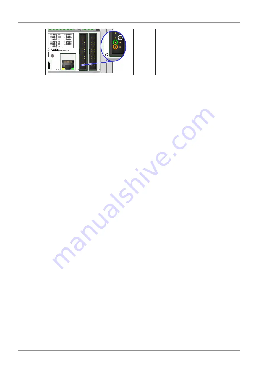
X2 inter-
face

Type

UART

Application

Serial 5 V TTL UART connection (8N1,
115,200 bauds)

Orange: GND
Green: RX
White: TX

6.5   Installing the Software

ü

Basic requirements for using the software: Windows 7/10 64-bit and Java Runtime Environment >
1.8.0.

1. Connect the stick to the PC.

2. Extract the zip file on your local drive.

3. Install the driver 

dpinst-amd64.exe

 to use the control element via USB.

4. Select the suitable driver for your system.

ð

If you have Java Runtime Version > 1.8.0, select the following file: 

Gripper_1_0_1_25

(size: approx. 5 MB (6 MB extracted))

ð

If you do not have Java Runtime Version > 1.8.0, select the file: 

OFG_Gripper_1_0_1_25_bundled

(size: approx. 80 MB (190 MB extracted))

5. Start the file 

“Gripper_1_0_1_25.exe” 

(note: The numbers of the last two digits may be higher due to

changes).

6.6   Connecting the PC and Controller

1.

 Before starting the software, connect the OFG controller to your computer using a USB cable (see acces-

sories).

2. 

Windows automatically assigns a specific COM port to the controller used. To connect the controller to

the software, you must know the correct COM port.

Summary of Contents for OFG

Page 1: ...Controller OFG Operating Instructions WWW SCHMALZ COM EN US 30 30 01 02599 00 07 21 ...

Page 2: ...lished thereby Repro duction of the contents in full or in part is only permitted within the limits of the legal provisions of copyright law Any modifications to or abridgments of the document are prohibited without explicit writ ten agreement from J Schmalz GmbH Contact J Schmalz GmbH Johannes Schmalz Str 1 72293 Glatten Germany T 49 7443 2403 0 schmalz schmalz de www schmalz com Contact informat...

Page 3: ... Movement Path of the Gripper Fingers 14 5 Transport and Storage 15 5 1 Checking the Delivery 15 5 2 Transport 15 6 Installation 16 6 1 Installation Instructions 16 6 2 Mechanical Attachment 16 6 3 Pneumatic connection 17 6 4 Electrical Connection 18 6 4 1 Establishing the Electrical Connection for the Controller OFG via the Connection Distribu tors 18 6 4 2 Assignment of Terminals and Positions o...

Page 4: ...Contents 4 40 EN US 30 30 01 02599 00 07 21 8 Maintenance Plan and Cleaning 34 9 Warranty 35 10 Accessories 36 11 Taking the Product Out of Operation and Disposal 37 12 EU Conformity 38 ...

Page 5: ...ocumentation must be ac cessible to personnel at all times 3 Pass on the technical documentation to subsequent users ð Failure to follow the instructions in these Operating instructions may result in life threatening in juries ð Schmalz is not liable for damage or malfunctions that result from failure to heed these instructions If you still have questions after reading the technical documentation ...

Page 6: ... will result in death or serious injury if not avoided WARNING Indicates a medium risk hazard that could result in death or serious injury if not avoided CAUTION Indicates a low risk hazard that could result in minor or moderate injury if not avoided NOTE Indicates a danger that leads to property damage 1 5 Symbol This symbol indicates useful and important information ü This symbol represents a pr...

Page 7: ...articular the following are considered non intended use 1 Use in potentially explosive atmospheres 2 Unauthorized refits 2 3 Personnel Qualifications Unqualified personnel cannot recognize dangers and are therefore exposed to higher risks The operating company must ensure the following points The personnel must be commissioned for the activities described in these instructions The staff must be at...

Page 8: ...ectors 4 Only operate the integrated ejectors in the controller with a silencer CAUTION Risk of a gripping finger bursting if the air pressure is too high when the gripping fingers are activated Risk of injury 4 Ensure that the pneumatic connection is operated with a maximum air pressure of 1 6 bar 4 Wear ear plugs and protective glasses CAUTION Falling product Risk of injury 4 Fasten or store the...

Page 9: ...s The controller STEU OFG must be connected to the safety technology for the robot to ensure work can be performed safely The controller switches off the system if the necessary functions are unavailable 2 6 Modifications to the Product Schmalz assumes no liability for consequences of modifications over which it has no control 1 The product must be operated only in its original condition as delive...

Page 10: ... allows you to operate an OFG finger gripper manually 1 2 4 3 5 1 ROTARY SWITCH POS 1 2 ROTARY SWITCH POS 2 3 NEUTRAL BUTTON 4 POS BUTTON 1 5 POS BUTTON 2 Manual Activation You can use the two rotary switches 1 and 2 to select various preset profiles for closing and opening In this case the rotary switches have the same function choose the same profiles The profiles in the negative range open the ...

Page 11: ...1 the left rotary switch is assigned to the clos ing process and connection A3 and item 2 the right rotary switch is assigned to the opening process and connection A4 The three buttons are used to execute the set levels Button 4 left Activates gripping by the finger gripper with the level between 1 and 3 that is selected on the rotary switch item 1 Button 5 right Activates the opening of the finge...

Page 12: ...unoiled in accordance with ISO 8573 1 2001 class 7 4 4 Pneumatic connection VSL 8 6 Finger gripper connection VSL 8 6 Suction cup connection for Combo VSL 8 6 Sound pressure level dbA 85 70 Controller Normally open NO vacuum on fingers open with the Combo suction is also ON on the suction cup Mass kg 1 7 2 5 2 6 4 2 Dimensions Part no H L B X1 Y1 d d1 10 01 51 00005 67 275 162 5 260 122 9 9 10 01 ...

Page 13: ... 40 4 3 Finger Position vs Control Level Control level gripper positions Finger position in mm Operating range Close Open The curve shown here corresponds to an idealized course The actual curves of the respective applications may deviate from this ...

Page 14: ...99 00 07 21 4 4 Movement Path of the Gripper Fingers Vertical movement in mm Horizontal movement in mm Close Open The curve shown here corresponds to an idealized course The actual curves of the respective applications may deviate from this ...

Page 15: ...ery with the supplied delivery notes to make sure nothing is missing 2 Damage caused by defective packaging or occurring in transit must be reported immediately to the carrier and J Schmalz GmbH 5 2 Transport Flawless and dust free containers must be used for transport to and from the installation site and profes sional safety measures must be ensured Only means of transport that comply with the s...

Page 16: ... unauthorized restart For safe installation the following instructions must be observed 1 Use only the connections mounting holes and attachment materials that have been provided 2 Carry out mounting and removal only when the device is in an idle depressurized state 3 Pneumatic and electrical line connections must be securely connected and attached to the Controller OFG 6 2 Mechanical Attachment T...

Page 17: ...e device Basic 2 1 Control 1 2 Combo Version ü The appropriate hoses are ready for use For the compressed air connection and the connection for the finger gripper OD 8 mm ID 6 mm For the vacuum connection for the suction cup OD 8 mm ID 6 mm 1 Connect the pneumatic hose for the com pressed air supply to the connection 1 note the marking on the device 2 Connect the pneumatic hose for the finger grip...

Page 18: ...not connect or disconnect the connector under tension and or when voltage is ap plied 6 4 1 Establishing the Electrical Connection for the Controller OFG via the Connection Distributors To establish the electrical connection for the respective controller first remove the cover 1 Remove the cover for the Basic version Un screw and remove the two screws shown in the figure 2 Carefully remove the cov...

Page 19: ...serial 5 V TTL UART connection 8N1 115 200 bauds 2 On the terminals 1 to the right and left of the PLC 24 V DC and ground DI for gripping and releasing Analog input 0 to 10 V feedback pressure reached 1 The profiles can be changed only using the software or a terminal program Combo Version 1 On the PLC 2 Gripper profiles1 Neutral position USB and serial 5 V TTL UART connection 8N1 115 200 bauds Su...

Page 20: ... gripper pos 31 02 Mass AI9 Go to gripper pos 41 03 Pressure on close finger AI10 Go to gripper pos 51 04 Vacuum on open finger AI11 Go to gripper pos 61 05 Analog In 0 to 10 V DI0 Neutral position 06 Feedback DI2 Suction cup on 24 V on 0 V off 2 Red mark ing AI6 Go to gripper pos 11 DI3 Blow off off 24 V on 0 V off 2 AI7 Go to gripper pos 21 Blue mark ing X2 5 V TTL UART serial connection 8N1 115...

Page 21: ...en 2 AI8 24 V the gripper position goes to 0 fixed gripper position in neutral position 3 Default setting 50 neutral position 2 AI9 24 V the gripper position goes to 1 can be selected in in crements of 1 between 50 and 100 3 Default setting 80 38 5 mm closed 2 AI10 24 V the gripper position goes to 2 can be selected in in crements of 1 between 50 and 100 3 Default setting 90 42 mm closed 2 AI11 24...

Page 22: ... for your system ð If you have Java Runtime Version 1 8 0 select the following file Gripper_1_0_1_25 size approx 5 MB 6 MB extracted ð If you do not have Java Runtime Version 1 8 0 select the file OFG_Gripper_1_0_1_25_bundled size approx 80 MB 190 MB extracted 5 Start the file Gripper_1_0_1_25 exe note The numbers of the last two digits may be higher due to changes 6 6 Connecting the PC and Contro...

Page 23: ...ection search for Arduino Mega In the paren theses you can see the COM port windows assigned to your con troller here COM 5 The name Arduino Mega is dis played only if the driver dpinst amd64 exe is installed If it is not installed Serial USB connection COMx connection is displayed for example 5 You can now run the exe file You can see the operating screen which is divided into vari ous sections a...

Page 24: ...n 24 40 EN US 30 30 01 02599 00 07 21 6 To connect the controller to the software go to Settings to select the assigned COM port 7 Click Port scan to scan all the COM ports that are currently as signed by Windows ...

Page 25: ...vice Manager 9 Please go to the Windows COM port assigned to your here COM5 controller if necessary click or v save it and connect it 1 2 10 Display for the connection The serial monitor displays a se ries of commands that end with logged on In addition a blue dot is displayed in the top right corner The software can be used see the chapter Operation for informa tion about using it ...

Page 26: ...ol via Signal Inputs Direct control of pins AI6 to AI11 means that preprogrammed positions can also be performed directly via 24 V signal 6 The signal should be applied for at least 100 ms before falling off again Use pin DI0 to perform neutralization again The software allows you to configure the 6 gripper positions via the USB interface 7 4 Control via Analog Input You can use an analog voltage ...

Page 27: ...ositions G132 A35 B42 C50 D65 E80 F90 G133 P time Store precharge discharge time in ms to EPROM 1 m 10 ms G133 P20 M1 M6 Go to defined position 1 to 6 M20 Vacuum suction cup ON OFF M21 Vacuum suction cup auto ON M22 Vacuum suction cup Auto OFF M40 Version and status M65 X number de lay Demo mode for testing M65 X100 D250 M116 Debug off M117 Debug on show feedback time All commands must end with a ...

Page 28: ... with a vacuum range of 25 to 49 Fixed neutral position 50 3 profiles for closing the finger with pressure range of 51 to 100 Save transfer new profiles to PLC 1 Changing parameters Click the dark blue area to change the parameter The light blue bar is displayed on the cursor position The number shows the control position 2 Activating the finger gripper Activate the fin ger gripper by clicking its...

Page 29: ...n two setpoints to simulate the process 1 To change the parameters click the high lighted positions in the light blue bar You change the setpoints by moving them to the right or left The number shows the control position 2 Alternatively use the arrow keys on your key board to activate the various processes This is indicated by the arrows next to the operation v c Section 3 Set Air Hose Length Adap...

Page 30: ... This is the feedback time that the PLC waits until the valve sends a feedback signal to the PLC indicating that the set pressure is reached If the valve reaches the set pressure within the set feedback time default 1000 ms the following feedback is displayed 24 V via terminal DO06 Message on the serial monitor purple area with the actual feedback time if debug mode was ac tivated with the Debug O...

Page 31: ... them and save the correct COM port to use the software How do you know the COM port is the correct one Open the Microsoft Windows Device Manager to dis play the devices that are currently connected Search for Arduino Mega in the Connections section 3 Area in black frame If more than one controller is used by a computer you can specify and save ten different units To change the unit use the and bu...

Page 32: ...f a gripping finger Factory Reset Resets everything in the controller to the fac tory settings DEMO This starts demo mode in which the gripper is opened and closed 10 000 times with a short idle time in between Number of cycles 10 000 Gripping finger positions Switches be tween position 1 and position 2 Length of the pneumatic hose as saved Waiting time between opening and clos ing 200 ms 5 Area i...

Page 33: ...pos2 C pos3 D pos4 E pos5 F pos6 Save new gripper positions G132 A35 B42 C50 D65 E80 F90 G133 P time Save the precharge discharge time in ms 1 m 10 ms G133 P20 G134 T time Save feedback timeout in ms M1 M6 Go to defined position 1 to 6 M20 Suction cup ON OFF M21 Vacuum suction cup auto on M22 Vacuum suction cup auto off M40 Version and status M65 X number D delay Demo mode for testing M65 X100 D25...

Page 34: ...ust comply with the legal regulations and safety regulations applicable at the location of use These intervals apply to single shift operation For heavier use such as multi shift operation the intervals must be shortened accordingly Maintenance task Daily Weekly Monthly Every six months Yearly Check the general condition of the en tire system before starting work Per form a visual inspection for d...

Page 35: ... 40 9 Warranty Schmalz guarantees this system pursuant to our General Terms and Conditions of Sale and Delivery The same applies to spare parts provided that these are original parts supplied by us Wearing parts are not covered by the warranty ...

Page 36: ...eck the proper functioning of the product especially the safety features after every maintenance or troubleshooting operation Designation Part no Connection cable ASK S M8 4 2000 K 4P 21 04 05 00150 Connection cable ASK S M12 5 2000 K 5P Turck WASS4 5 2 S366 21 04 05 00175 Power supply unit 21 07 01 00021 Pneumatic hose VSL 8 6 PU 10 07 09 00003 Connection cable ASK S USB A 2000 S USB B 21 04 05 0...

Page 37: ...e fully disassembled and disposed of Only qualified specialist staff may prepare the product for disposal 1 Fully disconnect the product from the power supply 2 Dispose of the components properly based on their material groups For proper disposal contact a company specializing in the disposal of technical goods and instruct the company to observe the applicable disposal and environmental regulatio...

Page 38: ...ere applied EN ISO 12100 Safety of machinery General principles for design Risk assessment and risk reduction EN 60204 1 32 Safety of machinery Electrical equipment of machines EN IEC 63000 Technical documentation for the assessment of electrical and electronic products with respect to the restriction of hazardous substances The EU Declaration of Conformity valid at the time of product delivery is...

Page 39: ...30 30 01 02599 00 09 21 39 40 ...

Page 40: ... J Schmalz GmbH EN US 30 30 01 02599 00 07 21 Subject to technical changes without notice ...

Reviews: