background image

KC9116/KC9116-2 & KC9326/KC9326-2 INSTALLATION

Installing the KC9116/KC9116-2 or KC9326/KC9326-2

57044-C                                              Page 8                                              04-2007


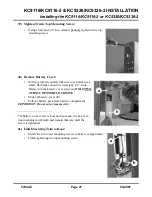
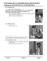
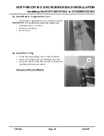
6)  Install the Key Cylinder:

Table 1: Blocking Rings

Table 2: Recommended Cams

7)  Align Key Cylinder:

Key Cylinder Length

Blocking Ring (Schlage P/N; XXX = finish)

•     1-1/4”

1/8” (36-079-012-XXX)

•     1-3/8”

1/4” (36-079-025-XXX)

•     1-1/2”

3/8” (36-079-037-XXX)

•     1-5/8”

1/2” (36-079-050-XXX)

Cylinder/Core

Schlage Type

Part Number

•     Standard Mortise Cyl

Everest

L583-153

•     Standard Mortise Cyl

Classic

L583-254

•     Interchangeable Core

IC Cam

L583-255

•     

Install .050” cylinder washer.

IMPORTANT: A .050” cylinder washer must be used IN ALL CASES, 
regardless of the key cylinder length.

•     

If you are installing a cylinder that is longer than 1-1/8”, you 

must also install a blocking ring (see 

Table 1: Blocking 

Rings, on page 8

).

A simple formula for determining blocking ring thickness is:

Blocking ring thickness = length of cylinder minus 1-1/8”

•     

 If not already done, install cam onto cylinder. Cam must be clo-

ver leaf design (see 

Table 2: Recommended Cams, on page 8

).

•     

Tilt top of trim down at a sharp angle.

•     

Screw in key cylinder until it stops. Use mechanical key as a han-

dle for turning if necessary.

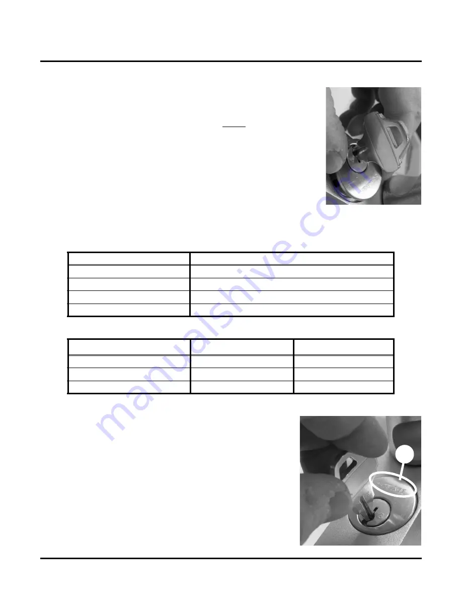
•     

After screwing it all the way in, back off on key cylinder 

(no more than one turn) until key is at the bottom. If key 
cylinder has a logo (

a

), logo should be at the top of key 

cylinder.

a

Summary of Contents for KING COBRA KC9116

Page 1: ...KING COBRA KING COBRA 2 NARROW STILE SERIES 57044 C 04 2007 KC9116 KC9116 2 KC9326 KC9326 2 Keypad Programmable and SNAP Compatible Trim For Narrow Stile Doors ...

Page 2: ...KC9116 KC9116 2 KC9326 KC9326 2 INSTALLATION Contents of the Box 57044 C Page 2 04 2007 KC9116 KC9116 2 KC9326 KC9326 2 INSTALLATION Contents of the Box ...

Page 3: ... lever or turnpiece will be continuously engaged allowing latched passage mode until a toggle code or iButton is entered again to relock the trim The KC9116 KC9116 2 trim w lever and the KC9326 KC9326 2 trim w turnpiece are both compatible with Von Duprin old style 3347 3547 concealed vertical rod exit devices Tools and Materials Needed Contact Information Schlage Lock Company 575 Birch Street For...

Page 4: ...es left in the door If the KC9326 KC9326 2 trim w turnpiece is used and the existing pull b must be removed Ives offers a compatible pull Schlage Cover Plate P N KC9000 KRP Ives Pull P N 8190 18 xxx xxx finish b a Refer to existing Von Duprin prep Use template or dimen sions below to remove required material from the outside of the door Do not remove material from the exit device side ...

Page 5: ...mat IC core w cam Schlage 80 108 FINISH NOTE This core requires the use of 1 4 blocking ring Schlage 36 079 025 FINISH Full Size IC core w cam Schlage 30 016 FINISH NOTE This core requires the use of 3 8 blocking ring Schlage 36 079 037 FINISH The KC9000 can use a 1 1 8 mortise cylinder without the use of a blocking ring For cylinders longer than 1 1 8 a blocking ring is required The blocking ring...

Page 6: ... Do not remove any of the screws in the fol lowing step or it will be difficult to reinstall them Using a small Philips head screwdriver loosen screws a b in baseplate around key cylinder hole one turn NOTE Screws a b c d are set at the factory Screws a b are tightened and screws c d are left loose b d a c The key cylinder that you install must be 1 1 8 long or longer Do not attempt to install a k...

Page 7: ... nose pliers push dead latch towards the top end of trim as indicated by arrow in photo NOTE As indicated by arrow in photo you ll notice that when you push the dead latch forward it will swing a little bit in a counterclockwise direction a To insure that dead latch is placed far enough out of the way to allow key cylinder to be threaded in properly Insert a finger into key cylinder hole and hold ...

Page 8: ... 050 cylinder washer must be used IN ALL CASES regardless of the key cylinder length If you are installing a cylinder that is longer than 1 1 8 you must also install a blocking ring see Table 1 Blocking Rings on page 8 A simple formula for determining blocking ring thickness is Blocking ring thickness length of cylinder minus 1 1 8 If not already done install cam onto cylinder Cam must be clo ver ...

Page 9: ...screws in the fol lowing order Tighten a and b until snug Tighten c and d until snug Fully tighten a and b Fully tighten c and d Check all four screws to make sure that all four are completely tight b c a d For clarity purposes only photo on the right is a view of deadlatch with escutch eon removed Edge a is referred to as the dead latch s critical edge IMPORTANT In the next step the critical edge...

Page 10: ...own in photo on right Look closely at edge of dead latch s critical edge a when doing this IMPORTANT When the dead latch s critical edge is correctly aligned the dead latch s set screw hole will likewise be correctly aligned Photos A B and C below illustrate examples of an incorrectly aligned critical edge Photo D is an example of a correctly aligned critical edge a NOT CORRECTLY ALIGNED NOT CORRE...

Page 11: ...as far as it will go and it is protruding beyond the surface of baseplate as shown in photo B the most probable cause is that dead latch was not positioned properly seePosition the Dead Latch s Set Screw Hole on page 10 If you have turned the set screw in as far as it will go and it is protruding from the surface of the baseplate do the following Turn set screw back out so that about 1 4 is pro tr...

Page 12: ...s Reverse NOTE All narrow stile trim is Reverse Once the handing of the installation is determined you may have to change the location of the stop screw in the baseplate To change the location of the stop screw Use a 3 32 Allen wrench For RHR installations Refer to photo on the right for stop screw location a a b For LHR installations Refer to photo on the right for stop screw location b for LHR I...

Page 13: ... Secure the Lever Cover Determine correct orientation for door and lock hand and slide lever onto shaft accordingly NOTE A RHR installation is shown in the photo on the right Using a 5 64 hex wrench tighten the set screw IMPORTANT After set screw has been completely tightened top of set screw should be at or a little bit below surface of lever If not check to insure that lever is pushed completely...

Page 14: ...ing a Philips head screwdriver remove and retain the screws that secure the centercase covers a Remove and retain the centercase covers Remove existing trim if present a Locate horizontal centerline of device Transfer horizontal centerline to side of door Measure backset on exit device side using square Transfer backset measurement to the trim side NOTE Take door bevel into account if there is one...

Page 15: ...emplate against door Mark drill point for 3 4 hole NOTE If existing Von Duprin trim prep is present proceed to Place Vertical Rod in Latched Position on page 15 Remove template A Drill 3 4 hole IMPORTANT Use care not to damage the device as there are parts inside door in this area NOTE If drilling a pilot hole first do not use a drill smaller than 1 4 This will prevent accidental damage to the thr...

Page 16: ...Page 16 04 2007 25 Install Alignment Tool 26 Apply Template B Screw in the provided alignment tool into threaded hole as far as it will go Place template B over alignment tool Verify that template is lined up vertically and horizontally If present leave existing sex bolts in place Tape template B to door ...

Page 17: ...nter Area 29 Remove Material in Center Area Mark the drill points for the three 10 32 holes NOTE Omit center hole if Von Duprin trim prep is present Mark the four 1 4 holes for the center area NOTE Only mark the two top holes if Von Duprin prep is present Drill the holes that you marked for the center area Remove all material inside rectangle IMPORTANT Use care not to damage exit device ...

Page 18: ...Holes 31 Insert Position Actuator Plate 32 Tighten Actuator Screw Drill and tap the holes in step Mark Drill Points For the 10 32 Holes on page 17 With 10 24 screw inserted in actuator plate hold screw in place with screwdriver Carefully insert actuator plate into prep Position rod actuator Fully tighten the screw in the actuator plate ...

Page 19: ...6 KC9326 2 57044 C Page 19 04 2007 33 Apply Gasket 34 Place Spacer Plate Onto Trim 35 Position the Trim Peel backing from gasket Apply gasket a to trim a Place spacer plate a onto trim a Hold trim at an angle Slide trim s actuator tip a under rectangular hole Swing trim into position a ...

Page 20: ... exit device back onto door Verify that exit device engages with trim NOTE It may be necessary to turn the lever or turnpiece a little to properly engage the exit device with the trim Hold trim in place Using two 1 4 20 flat head screws and a Philips head screwdriver secure trim to exit device Place centercase covers back onto centercase Using a Philips head screwdriver secure covers with the scre...

Page 21: ...ed counterclockwise in cylinder use a small flat blade screwdriver straight 1 8 wide blade turn the battery cover screw a ONLY TWO TURNS COUNTERCLOCKWISE Slide off battery cover b Pull out battery pack from battery compartment IMPORTANT Do not cut or remove wire If battery cover screw is loosened too much the key over ride mechanism will jamb and remain that way until the screw is tightened a b In...

Page 22: ...RTANT THAT IT IS REINSTALLED AFTER THE BATTERIES ARE INSTALLED IN BATTERY HOLDER Observe the polarity markings indicated on battery holder and install four AAA batteries accordingly Slide battery bag onto battery holder Fold battery bag over The battery bag is used to protect the batteries from mois ture and to insulate them electrically from metallic parts Install battery pack into compartment wi...

Page 23: ...lug Slide battery compartment cover on from the bottom IMPORTANT Use caution not to pinch the battery wire Tighten battery cover screw Rotate key clockwise Remove key Verify that top mounting screw is fully tightened Insert water plug a into top mounting screw hole Using the end of a small Allen wrench or similar tool push plug into hole past surface INSTALLATION COMPLETE a ...

Page 24: ...ece should retract latch The key should only rotate counterclockwise not clockwise If you find that this is not correct see Partially Tighten the Set Screw on page 11 4 Rotate key back to original position and remove it Lever turnpiece should no longer retract latch 5 Using the keypad enter the default access code 1 3 5 7 9 The red LED should light each time the first four numbers are pressed and ...

Reviews: