background image

14  •  Schlage  •  AD-200 user guide

Wired remote release feature

System and hardware requirements

•  Available on AD200 storeroom function only

•  Compatible with AD200 hardware revision F or higher. See illustration below to locate 

revision letter on main printed circuit board.

•  The AD200 must be programmed with AD-200 version 2.45.1 firmware or higher.

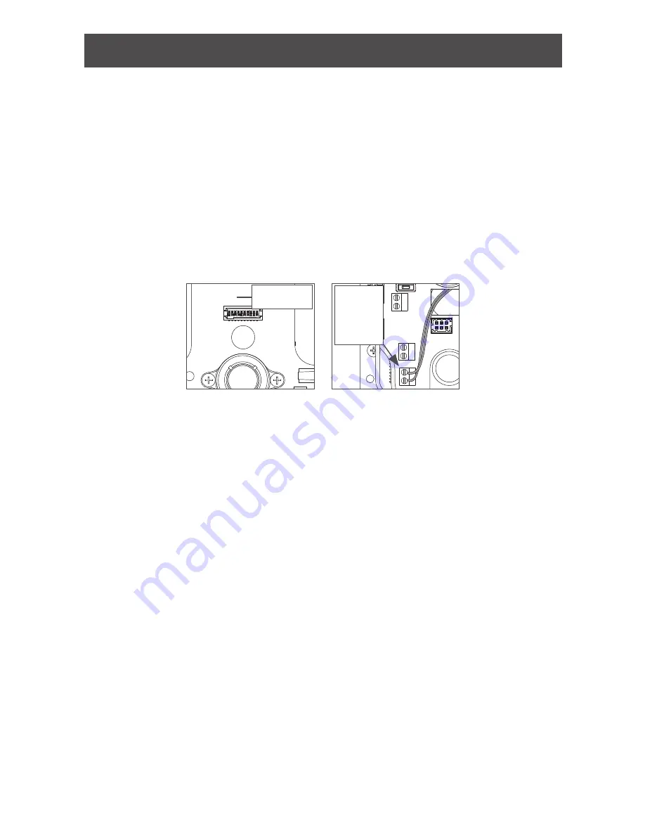
Switch specifications, wire specifications and routing

•  Recommended switch: basic SPST (single-pole single-throw) momentary action switch 

with normally open contact configuration.

•  Wire gauge AWG 24, stranded, twisted pair, shielded (shield may be left unterminated).

•  Belden 9841 or equivalent.

•  Maximum cable length is 1000 feet (305 meters).

•  Route wires from the switch, through the door frame and door to the latch bolt terminals 

as shown below.

AUX POWER

LA

TCH BOL

T

RESET

DPS

DEADBOL

T

23394042

REV F

RESET

RESET

RESET

Hardware 

revision letter

AUX POWER

LA

TCH BOL

T

RESET

DPS

DEADBOL

T

23394042

REV F

RESET

RESET

RESET

Attach 

the switch 

wires to 

latch bolt


terminals

Wired remote release operation

IMPORTANT! The remote release feature will function only when the AD-200 inside cover is 

completely and properly installed.

Operation with firmware version 2.45.1

•  When the remote release button is pressed the lock will unlock for the programmed 

relock delay period. The Schlage LEDs will flash green once to indicate the lock is 

unlocked. The beeper will not sound.

•  After the relock delay period has expired, the Schlage LEDs will flash red once to 

indicate the lock is relocked.

Operation with firmware version 2.46.1

•  When the remote release button is pressed the lock will unlock for the programmed 

relock delay period. The green Schlage LEDs and the green inside push button LED will 

turn on to indicate the lock is unlocked. If the beeper function is turned on, the beeper 

will sound one time to indicate the lock is unlocked.

•  After the relock delay period has expired, the green Schlage LEDs and the green inside 

push button LED will turn off. If the beeper function is turned on, the beeper will sound 

two times to indicate the lock is relocked.

Wired remote release button action

•  If the remote release button is pressed and held, the release will function only one time, 

even in the event the button is held longer than the relock delay period.

•  If the remote release button is quickly pressed repeatedly, the release will function only 

one time. Any additional button presses during the relock delay period are ignored.

•  Once the lock relocks, the next press of the remote release button will activate a new 

release cycle.

Summary of Contents for AD-200

Page 1: ...6 129 AD 200 AD 201 Offline lock user guide Instructions for AD Series offline locks Para el idioma español navegue hacia www allegion com us Pour la portion française veuillez consulter le site www allegion com us ...

Page 2: ...mote release feature 14 System and hardware requirements 14 Switch specifications wire specifications and routing 14 Wired remote release operation 14 Wired remote release button action 14 Reset to factory defaults 15 Level 1 factory default reset 15 Level 2 factory default reset 15 Batteries 16 To install or replace batteries 16 Low battery indications 17 Battery failure modes 17 External power s...

Page 3: ...k maintains an audit trail of events Configured using the Schlage Utility Software SUS Outside Schlage Button Outside Lever Keyway Inside Optional Inside Push Button IPB Thumbturn Inside Lever Battery Compartment Keypad Multi Tech Reader Mag Card Insert Reader Mag Card Swipe Reader AD 200 993 AD 200 CY AD 200 MS AD 200 MD Additional AD 200 reader options Mag Keypad Multi Tech Keypad Note Proximity...

Page 4: ...isit www allegion com us see Support Schlage Electronics Electronic Locks Technical Library for more information 2 Make sure the batteries are installed properly See Batteries on page 16 for instructions 3 Configure the master construction credential where applicable See Construction access mode on page 5 for more information The lock should remain in construction access mode until you are ready t...

Page 5: ...redential is created or the lock is programmed with the SUS Locks with card readers Create a master construction credential The master construction credential is used to program construction access mode credentials To create a master construction credential 1 Press and hold the Schlage button while presenting a credential 2 The Schlage button will blink green on the left and right as confirmation ...

Page 6: ...le functions Credential type Function Programming PIN or card Used only to program the lock Does not unlock the lock Normal use credential Unlocks the lock momentarily after a credential is presented or entered Toggle credential Changes the state of the lock from locked secured to unlocked unsecured or vice versa unless in a Freeze state Freeze credential Freezes the lock in the current state The ...

Page 7: ...2 to interpret error code patterns L L A unique credential must be used for each credential type for example a single credential may not be used for both normal use and toggle functions PROGRAMMING credentials To complete this action Perform the following steps Wait for to stop flashing between each step 1 2 3 4 Create new Programming Code PIN Enter This is the default programming PIN Enter Enter ...

Page 8: ...ther PIN go back to step 3 Press again to finish Wait for confirmation 2 right green blinks Create a Normal Use CARD Enter Programming PIN and OR Present Programming card Enter Enter new 3 6 digit Card ID Number and Wait for right green light Present new CARD to lock For another CARD go back to step 3 OR press again Wait for confirmation 2 right green blinks Create a Normal Use CARD Card ID Number...

Page 9: ... 3 OR press again to finish Wait for confirmation 2 right green blinks Create a Toggle CARD Enter Programming PIN and OR Present Programming card Enter Enter Enter new 3 6 digit Card ID Number and Wait for right green light Present new CARD to lock For another CARD go back to step 3 OR press again to finish Wait for confirmation 2 right green blinks Create a Toggle CARD Card ID Number Enter Progra...

Page 10: ... 3 OR press again to finish Wait for confirmation 2 right green blinks Create a Freeze CARD Enter Programming PIN and OR Present Programming card Enter Enter Enter new 3 6 digit Card ID Number and Wait for right green light Present new CARD to lock For another CARD go back to step 3 OR press again to finish Wait for confirmation 2 right green blinks Create a Freeze CARD Card ID Number Enter Progra...

Page 11: ... 3 OR press again to finish Wait for confirmation 2 right green blinks Create a Pass Through CARD Enter Programming PIN and OR Present Programming card Enter Enter Enter new 3 6 digit Card ID Number and Wait for right green light Present new CARD to lock For another CARD go back to step 3 OR press again to finish Wait for confirmation 2 right green blinks Create a Pass Through CARD Card ID Number ...

Page 12: ...the total delay time Example adds a 10 second delay Press again to finish Wait for confirmation 2 right green blinks Error codes L L All error codes are indicated on the Schlage button by a solid red left LED and a blinking green right LED The number of green blinks indicates the error code Number of green blinks Error code description Red Left LED Green Right LED 1 Computer programming error not ...

Page 13: ...for 20 seconds awaiting the presentation of another credential to be granted Construction User Access 2 When a valid construction access user credential is presented the lock will unlock for the re latch delay period default three seconds and the left side of the Schlage button will blink green When the lock relocks after the relock delay period the left side of the Schlage button will blink red 3...

Page 14: ...are version 2 45 1 When the remote release button is pressed the lock will unlock for the programmed relock delay period The Schlage LEDs will flash green once to indicate the lock is unlocked The beeper will not sound After the relock delay period has expired the Schlage LEDs will flash red once to indicate the lock is relocked Operation with firmware version 2 46 1 When the remote release button...

Page 15: ...ill occur with each press 5 The Schlage button and IPB will both light green for one second and a one second beep will be heard This indicates that the lock has been reset L L If the IPB is not pressed 3 times within 10 seconds two beeps with two red blinks indicate timeout 6 Replace the top inside cover Level 2 factory default reset L L Level 2 factory default reset will delete all configurations...

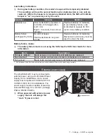
Page 16: ...ch the battery wires when installing the battery cover CAUTION Danger of explosion if battery is incorrectly replaced Replace only with the same or equivalent type Dispose of used batteries according to the manufacturer s instructions Four Battery Configuration Eight Battery Configuration This product has been evaluated for ULC S319 compliance with AA and coin cell batteries listed below For insta...

Page 17: ...nical override key must be used to unlock the lock Battery failure modes L L The battery failure mode is set using the SUS See the SUS User Guide for more information Mode Description Fail As Is default Lock remains in current state until batteries are replaced Fail Unlocked1 Lock unlocks and remains unlocked until batteries are replaced Fail Locked1 Lock locks and remains locked until batteries a...

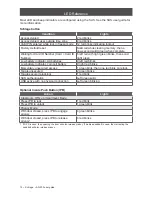
Page 18: ...ator AA batteries 9 left red blinks Low battery indicator coin cell battery 9 right red blinks Momentary unsecured access 1 green blink then one red blink on relock Toggle unsecured 2 green blinks Toggle secure relocking 1 red blink SUS authentication Left green solid USB active with no physical connection Left green blinking Optional Inside Push Button IPB Action Lights Classroom Office or Apartm...

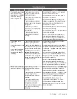
Page 19: ...y be pinched The Smart card default of the card reader may not be correct for the Smart card The Mag Track in Use default for all Magnetic Card Credential Readers is Track2 The magnetic swipe card data may be on Track1 or Track3 Check that the through hole ribbon cable is not pinched Change the Smart card format using the SUS Select AD 200 AD 201 Lock Properties Reader tab and Smart cards in use U...

Page 20: ...rotection against harmful interference in a residential installation This equipment generates uses and can radiate radio frequency energy and if not installed and used in accordance with the instructions may cause harmful interference to radio communications However there is no guarantee that interference will not occur in a particular installation If this equipment does cause harmful interference...

Reviews: