background image

Connections 


©

 by Antriebs- & Regeltechnik Schimpf GmbH 


25 

Connections 

The national regulations for electrical installations must be observed when connecting 

the  actuating  drives.  The  actuating  drives  may  only  be  connected  by  a  qualified 

electrician. Follow the connection diagram in the cover and the technical guidance on 

the outside of the actuating drive. 


Figure 5: Circuit diagram, simplified 


Summary of Contents for 00-10/30 STEP

Page 1: ... drive 00 10 30 STEP Actuating drive 00 15 30 STEP Actuating drive 01 15 30 STEP Antriebs Regeltechnik Schimpf GmbH Bonholzstraße 17 71111 Waldenbuch Germany Tel 49 0 7157 52756 0 Fax 49 0 7157 52756 99 Email Info Schimpf Antriebe de ...

Page 2: ...Regeltechnik Schimpf GmbH This documentation includes specifications for the relevant products but does not guarantee that they have any particular properties We reserve the right to make technical changes Published in 05 2022 Liability and guarantee Antriebs Regeltechnik Schimpf GmbH accepts no liability or guarantee whatsoever in the event of the improper installation or use of the actuating dri...

Page 3: ... the end positions 14 Configuring the analogue inputs and outputs 15 Calibration of the analogue inputs and outputs 15 Setting the direction of rotation 16 Setting the other operating parameters 16 Setting the cam switches 16 00 10 only optional add on board 16 00 15 only optional add on board 20 01 15 only optional additional switches 23 Readiness for operation 23 Connections 25 Wiring diagram 00...

Page 4: ...ition in the event of a line break 45 Mode 5 Setting the speed 46 Mode 6 Setting the averaging 46 Mode 7 Setting the ramp 46 Mode 8 Setting the step size hysteresis 47 Mode 9 Setting the end positions 47 Configuration mode 2 53 Mode 0 Return to standard mode 55 Mode 1 Test 55 Mode 2 Calibrate analogue output 56 Mode 3 Calibrate analogue input 4 mA or 2 V value 59 Mode 4 Calibrate analogue input 20...

Page 5: ...General information by Antriebs Regeltechnik Schimpf GmbH 5 Motor monitoring 63 Plausibility check 64 Troubleshooting 65 Technical specifications 67 Declaration of Conformity 69 Dimensional drawings 70 ...

Page 6: ...onnected from mains power Before switching off devices machines systems it is important to check that it is safe to do so This is particularly important for process engineering systems Make sure that no vibrations occur during installation Shutdowns may only be carried out after prior consultation with the plant manager shift supervisor or safety engineer Malfunctions must be reported immediately ...

Page 7: ...alified and aware of this potential danger When working on open and ready to operate actuating drives no voltage may be applied to terminals 7 to 25 When working on open and ready to operate actuating drives only the 3 operating buttons and the 2 rotary switches may be used During all further work on an opened actuating drive all cables connected to the drive must be disconnected from mains power ...

Page 8: ...hanical position of the drive This applies in particular to the end positions After completing the installation or configuration work check that the actuating drive is functioning correctly Check compliance with the end positions if necessary Also check that any optional components are functioning properly Finally check that any safety devices are functioning properly to ensure that they are free ...

Page 9: ...ate professional qualifications The actuating drives may only be used for their intended purpose The actuating drives may only be used when securely fixed on the relevant fitting The actuating drives may only be operated in accordance with the values specified in the technical specifications The actuating drives must not be installed commissioned or adjusted on damaged supply lines or flanged syst...

Page 10: ...The actuating drives are equipped with an externally readable position indicator as standard a switchover between manual and automatic operation for servicing two potential free limit switches and two 01 15 three freely adjustable potential free additional switches The actuating drives are available for the following mains voltages AC 90 260 V DC 24 V As standard the actuating drives feature three...

Page 11: ...eltechnik Schimpf GmbH 11 Overview and definitions Figure 1 Device overview 00 15 also representative for 00 10 and 01 15 1 Motor 5 CPU board 2 Cable glands 6 Add on board 3 Position indicator 7 Base board 4 Operating elements ...

Page 12: ...ckwise from this perspective A drive with the setting direction of rotation left closes the actuator counterclockwise from this perspective Clockwise is abbreviated as CW below Counterclockwise is abbreviated as CCW below Relays or switch outputs each have a separate output for a contact that closes when triggered normally open and a contact that opens normally closed Normally open contacts are ab...

Page 13: ...hnical specifications at the end of this document Adapters for other shaft designs are also available An overview of the standard adapters can also be found in the Dimensional drawings at the end of this document Installing a Schimpf control valve To mount a Schimpf drive on a Schimpf control valve insert the square spindle at end of the valve shaft into the square socket of the drive Make sure th...

Page 14: ...Ø 9 13 mm into the housing The cable glands must then be tightened firmly The permissible outside diameter of the inserted cables must be observed The connections must be made in accordance with the instructions in the section Connections Important The protective conductor terminal 6 must always be connected Setting the end positions The end positions for Closed and Open are set at the factory to ...

Page 15: ...tion feedback between voltage and current 1 ON 2 OFF current mA 1 OFF 2 ON voltage V The desired operating mode of the analogue interface must be stored in the device settings in line with the instructions under menu item Mode 1 Setting the analogue signal in the section Configuration mode 1 The operating mode is set jointly for input and output Calibration of the analogue inputs and outputs The a...

Page 16: ...uration Mode under menu item Mode 2 Direction of Rotation Setting the other operating parameters If needed the other operating parameters torque safe position speed averaging ramp hysteresis and heating can be set by following the instructions in the section Configuration mode 1 Setting the cam switches The optional cam switches can be used for a number of purposes such as controlling an external ...

Page 17: ...two switches influence each other As a result the following procedure must be followed when setting the cam discs Restriction due to the narrow design With a standard opening angle of 90 both positions cannot be below 25 at the same time Likewise both positions must not be above 65 at the same time Important Switch off the power supply whenever you adjust the device with tools The cam switches of ...

Page 18: ... the supply voltage Move the drive to the 0 position by electrical rotation Move the actuator to the first position to be switched by electrical rotation For clockwise turning drives first move the actuator to the larger of the two positions For counterclockwise turning drives the actuator must be moved to the smaller of the two positions first Disconnect the supply voltage from the mains Turn the...

Page 19: ...itches Tighten the stud bolt S Connect the supply voltage Move to the second position to be switched by electrical rotation Disconnect the supply voltage from the mains Turn the thin cam disc N1 using adjusting screw F until switch S2 audibly switches Connect the supply voltage Check the set switching positions with electrical rotation ...

Page 20: ...N1 and N2 The switching positions are output via terminals 20 to 25 see Figure 11 Add on board 00 15 Figure 3 Overview of cam switch 00 15 The camshaft with cam discs N1 and N2 is fixed on the drive shaft with stud bolt S Cam disc N2 is always firmly connected to the camshaft Cam disc N1 can be moved relative to the camshaft using the adjusting screw F The switch S1 evaluates the position of cam d...

Page 21: ...the adjusting screw F to bring the lower thin washer N1 of the camshaft into congruence with the upper washer N2 If necessary loosen the stud bolt S until the camshaft can be turned on the drive shaft Connect the supply voltage Move the drive to the 0 position by electrical rotation Move the actuator to the first position to be switched by electrical rotation For clockwise turning drives first mov...

Page 22: ...se switching cam so that both switches S1 and S2 are not switched Now turn the loose switching cam counterclockwise CCW until switch S2 audibly switches Tighten the stud bolt S Connect the supply voltage Move to the second position to be switched by electrical rotation ...

Page 23: ... Switch off the power supply whenever you adjust the device with tools Move to the desired position Secure the cams on the shaft with stud bolt S Fine adjustments can be made with a screwdriver on adjusting screw F To do this turn the adjusting screw F until a slight click of the switch can be heard The switching positions are output via terminals 20 to 28 Figure 4 Optional additional switches 01 ...

Page 24: ...vement Analogue control with enable 3 point step with enable Analogue control ignore enable 3 point step ignore enable Manual movement ignore limit switch Close the housing cover and tighten the four 3 mm hexagon socket screws in the corners Ensure that the seal is correctly seated Important Before closing the housing cover disconnect all cables connected to the drive from mains power The installa...

Page 25: ...r electrical installations must be observed when connecting the actuating drives The actuating drives may only be connected by a qualified electrician Follow the connection diagram in the cover and the technical guidance on the outside of the actuating drive Figure 5 Circuit diagram simplified ...

Page 26: ...Connections by Antriebs Regeltechnik Schimpf GmbH 26 Wiring diagram 00 10 Figure 6 Base board 00 10 Figure 7 CPU board 00 10 ...

Page 27: ...Connections by Antriebs Regeltechnik Schimpf GmbH 27 Figure 8 Add on board 00 10 Wiring diagram 00 15 Figure 9 Base board 00 15 ...

Page 28: ...Connections by Antriebs Regeltechnik Schimpf GmbH 28 Figure 10 CPU board 00 15 Figure 11 Add on board 00 15 ...

Page 29: ...Connections by Antriebs Regeltechnik Schimpf GmbH 29 Wiring diagram 01 15 Figure 12 Base board 01 15 Figure 13 CPU board 01 15 ...

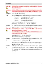
Page 30: ... There is a separation from PE Terminal 3 The external setpoint input current voltage is connected to terminal 3 of the base board The reference of the analogue signal is connected to terminal 2 Max input voltage 12 V current input Load 500 Terminal 4 DC device version 18 30 V DC The positive conductor of the DC supply voltage is connected to this terminal It is used to supply the drive with a con...

Page 31: ... for the three point step control and the enable signal terminals 11 12 and 13 is connected to this terminal Important For the DC device version a DC voltage 18 40 V DC must be applied to terminals 11 12 and 13 For the AC device version an AC voltage 110 265 V AC must be applied to terminals 11 12 and 13 AC version 90 260 V AC max current 5 mA DC version 18 30 V max current 10 mA Terminal 11 If a ...

Page 32: ... resistive load Terminals 17 18 19 Relay output R3 Min position This relay switches when the drive has reached the minimum position Terminal 17 Normally closed NC contact Terminal 18 Reference potential COM Terminal 19 Normally open NO contact AC switching capacity Max 250 V 500 mA resistive load DC switching capacity Max 220 V 500 mA resistive load Description of optional connections 00 10 Termin...

Page 33: ... 250 mA inductive load DC switching capacity 30 V 1000 mA resistive load Max 125 V 100 mA resistive load 30 V 500 mA resistive load Max 125 V 30 mA resistive load Terminals 23 24 25 Potential free output of switch 2 Terminal 20 Normally closed NC contact of switch 2 Terminal 21 Reference potential COM of switch 2 Terminal 22 Normally open contact NO of switch 2 AC switching capacity Max 250 V 500 ...

Page 34: ...potential COM of switch 2 Terminal 22 Normally open contact NO of switch 2 AC switching capacity Max 250 V 500 mA resistive load Max 250 V 250 mA inductive load DC switching capacity 30 V 1000 mA resistive load Max 125 V 100 mA resistive load 30 V 500 mA resistive load Max 125 V 30 mA resistive load Terminals 26 27 28 Potential free output of switch 3 Terminal 20 Normally closed NC contact of swit...

Page 35: ...plete or paused the housing cover must be replaced immediately Important When working on open and ready to operate actuating drives only the 3 operating buttons and the 2 rotary switches may be used During all further work on an opened actuating drive all cables connected to the drive must be disconnected from mains power The device is mainly operated using the three buttons S12 PROG S13 and S14 a...

Page 36: ...a mode other than 0 is selected the drive will be in configuration mode Rotary switch S11 Parameter In standard mode the desired operating mode is selected using the Parameter rotary switch In configuration mode the desired value is selected using the Parameter rotary switch Button S12 PROG In configuration mode settings are confirmed by pressing and holding this button Button S13 In the manual mo...

Page 37: ...Green In standard mode this LED signals a clockwise CW rotation of the drive In configuration mode the LED may perform special functions LED 4 Enable Green This LED will remain on as soon a voltage is applied to terminal 12 enable signal and an operating mode is set which takes the enable signal into account LED 5 Power Green This LED will remain on as soon as operating voltage is applied to the d...

Page 38: ...the position according to the analogue input signal at terminal 3 If no voltage is applied to terminal 12 enable signal the drive is in three point step mode If a voltage is applied to terminal 11 this causes the drive to rotate clockwise CW If the voltage is interrupted at terminal 11 or the end position is reached the rotary movement stops If a voltage is applied to terminal 13 this causes the d...

Page 39: ... point step mode If a voltage is applied to terminal 11 this causes the drive to rotate clockwise CW If the voltage is interrupted at terminal 11 or the end position is reached the rotary movement stops If a voltage is applied to terminal 13 this causes the drive to rotate counterclockwise CCW If the voltage is interrupted at terminal 13 or the end position is reached the rotary movement stops The...

Page 40: ...Regeltechnik Schimpf GmbH 40 Parameters 7 8 and 9 Parameters 7 8 and 9 are not assigned The drive is in idle mode The drive will not move regardless of the applied input signals The Ready for operation relay is not switched ...

Page 41: ...ges you make will only be permanently saved to the device when you set the Mode rotary switch back to 0 The Prog LED will flash briefly to show that your changes have been saved The actuator will then return to standard mode exception calibration values for the limit switches are saved immediately Settings such as torque speed averaging hysteresis and ramp influence each other to some extent These...

Page 42: ... 15 s 90 6 Average 0 sec Average 0 1 sec Average 0 2 sec Average 0 4 sec Average 0 6 sec Average 0 8 sec Average 1 0 sec Average 1 2 sec Average 1 5 sec Average 1 8 sec 73 Start stop ramp 0 05 sec Start stop ramp 0 2 sec Start stop ramp 0 4 sec Start stop ramp 0 6 sec Start stop ramp 0 8 sec Start stop ramp 1 0 sec Start stop ramp 1 2 sec Start stop ramp 1 5 sec Start stop ramp 2 0 sec Start stop ...

Page 43: ...42 Position 0 without triggering error relay Stop at current position Safe position 0 Safe position 10 Safe position 20 Safe position 30 Safe position 50 Safe position 70 Safe position 90 Safe position 100 5 Speed 90 s 90 Speed 80 s 90 Speed 70 s 90 Speed 65 s 90 Speed 60 s 90 speed 50 s 90 Speed 45 s 90 Speed 40 s 90 Speed 30 s 90 Speed 25 s 90 6 Average 0 sec Average 0 1 sec Average 0 2 sec Aver...

Page 44: ... Position 0 without triggering error relay Stop at current position Safe position 0 Safe position 10 Safe position 20 Safe position 30 Safe position 50 Safe position 70 Safe position 90 Safe position 100 5 Speed 90 s 90 Speed 80 s 90 Speed 70 s 90 Speed 65 s 90 Speed 60 s 90 speed 50 s 90 Speed 45 s 90 Speed 40 s 90 Speed 30 s 90 Speed 25 s 90 6 Average 0 sec Average 0 1 sec Average 0 2 sec Averag...

Page 45: ... direction of rotation is selected Parameter 0 Direction of rotation left Valve opens counterclockwise CCW Parameter 1 Direction of rotation right Valve opens clockwise CW Parameters 2 9 Not assigned when selected the current setting is not changed Mode 3 Setting the torque The torque is selected Parameters 0 9 Select the desired torque in 10 steps according to the Settings table The torques speci...

Page 46: ...peed is always related to a swivel range of 90 Mode 6 Setting the averaging The duration of the averaging process for the analogue setpoint input is selected Higher durations will use more individual measurements for averaging A higher setting can counteract any fluctuations in the input signal level Parameters 0 9 Selection of averaging in 10 steps from 0 s to 1 8 s Mode 7 Setting the ramp Use th...

Page 47: ...resis setting determines the level of precision with which the end positions are approached The higher the hysteresis setting the earlier the motor is switched off when an end position is reached In three point step mode and control mode this setting also determines the hysteresis of the end position relays Parameters 0 9 Select the hysteresis in 10 steps from 0 05 to 2 0 The values refer to an op...

Page 48: ...termining the position has a permissible range of motion of approx 110 It must be ensured that the end position does not lie outside the permissible range of motion of the drive The permissible range of motion of the potentiometer is shaded in red There are four markings on the potentiometer these are shown as red circles in the adjacent illustration The marking indicated with an arrow must always...

Page 49: ...on The LED will flash Once again ensure that the end position does not lie outside the permissible range of motion of the drive Press and hold the Prog button to set the new end position values The Prog LED will flash briefly Parameter 1 Configure individual end position CCW Mode 9 Parameter 1 This menu item is used to set a single end position in case only one of the two end positions needs to ...

Page 50: ...d end position as a blue arrow Ensure that the end position does not lie outside the permissible range of motion of the drive The Enable LED must be continuously lit If the current position is outside the valid range the Enable LED will flash twice There are four markings on the potentiometer these are shown as red circles in the adjacent illustration The permissible range of motion of the potenti...

Page 51: ...h In the example the end position to be set is shown as a red arrow and the second end position as a blue arrow Ensure that the end position does not lie outside the permissible range of motion of the drive The Enable LED must be continuously lit If the current position is outside the valid range the Enable LED will flash twice There are four markings on the potentiometer these are shown as red ci...

Page 52: ...Operation by Antriebs Regeltechnik Schimpf GmbH 52 Parameters 3 9 Not assigned when selected the current setting is not changed ...

Page 53: ...ton with the Mode and Parameter rotary switches set to 0 The PROG LED and the Enable LED will be on The Ready for operation relay is not switched You can then use the Parameter rotary switch to select different settings Press and hold the Prog button to save your settings The Prog LED will flash briefly to show that your settings have been saved To exit configuration mode 2 set the Mode and Parame...

Page 54: ...de 1 Test LEDs Validate current settings 2 Analogue output Calibrate current Analogue output Calibrate voltage 3 Analogue input current 4 mA calibrate value Analogue input voltage 2 V calibrate value1 4 Analogue input current 20 mA calibrate value Analogue input voltage 10 V calibrate value1 5 6 Motion 7 Heating off Heating on 0 Heating on 5 8 Restore factory settings 9 ...

Page 55: ... check is performed for all settings If an error is found in any of the settings the Ready for operation relay output drops out and the Error LED will turn on The flashing sequence of the Auto Enable LED will indicate an error number Flashing Error description 2x Drive position is outside the permissible range of motion 3x Operating data setting error detected analogue signal direction of rotation...

Page 56: ... calibrated at the factory Recalibrating the analogue output is usually only necessary if there are very high requirements for angular accuracy or for example if the connection cables are long Two calibration values can be adjusted in current or voltage mode for the calibration characteristic curve of the analogue output In current mode the calibration values for 4 mA and 20 mA can be adjusted In ...

Page 57: ... the value is stable Press and hold the Prog button to set the value The Prog LED will flash briefly The current 20 mA value is output The displayed value must be set to 20 mA as accurately as possible The value can be decreased using the button and increased using the button Wait until the value is stable Press and hold the Prog button to store the new calibration values for 4 and 20 mA in the me...

Page 58: ...ameter 1 Calibrate analogue output voltage Set Analogue DIP switch to voltage mode Connect voltmeter to analogue output terminals 1 and 2 The current 2 V value is output The displayed value must be set to 2 V as accurately as possible The value can be decreased using the button and increased using the button ...

Page 59: ...g the button Press and hold the Prog button to store the new calibration values for 2 and 10 V in the memory The Prog LED will flash briefly Parameters 2 9 Not assigned when selected the current setting is not changed Mode 3 Calibrate analogue input 4 mA or 2 V value The analogue input of the drive is calibrated at the factory Recalibrating the analogue input is usually only necessary if there are...

Page 60: ...the Prog LED will not flash Parameter 1 2 V is applied to the analogue input from a voltage source Press and hold the Prog button to store the new calibration values for 2 V in the memory The Prog LED will flash briefly If the new value is outside the valid range the new value cannot be stored in the memory the Prog LED will not flash Parameters 2 9 Not assigned when selected the current setting i...

Page 61: ... from a voltage source Press and hold the Prog button to store the new calibration values for 10 V in the memory The Prog LED will flash briefly If the new value is outside the valid range the new value cannot be stored in the memory the Prog LED will not flash Parameters 2 9 Not assigned when selected the current setting is not changed Mode 5 Not used Mode 6 Motion Parameter 0 The drive can be mo...

Page 62: ...0 C Parameter 2 The heating is activated as soon as the temperature in the device falls below 5 C Parameters 3 9 Not assigned when selected the current setting is not changed Mode 8 Restore factory settings Parameter 0 Press and hold the Prog button to reset all operating data analogue signal direction of rotation torque safe position speed averaging ramp hysteresis or heating and also the calibra...

Page 63: ...rred o Excess heat The temperature in the drive has risen to over 70 C In this case the drive will continue to move o Analogue input line break In this case the drive will behave in line with the setting Mode 4 Safe position in the event of a line break o Motor error e g blockage see the section Motor monitoring below o Error detected in plausibility check see the section Plausibility check below ...

Page 64: ... Plausibility check Each time the system is started the actuator performs a plausibility check for all of the settings Any error that is found in any of the settings will be automatically corrected if possible for example by resetting to factory settings The Ready for operation relay output will drop out and the Error LED will turn on The flashing sequence of the Auto Enable LED will indicate an e...

Page 65: ...nt mode or manual movement ignore limit switch mode Change to another mode No supply voltage to the drive Check the connection cables for the supply voltage Excess heat The temperature in the drive is over 70 C Let the drive cool down Analogue input line break Check the connection cables of the analogue input Motor error e g blockage Check the drive as well as the actuator for a blockage If necess...

Page 66: ...ting If necessary increase the Averaging setting The analogue output does not show the expected values The settings for the analogue signal are not set correctly If necessary adjust the Analogue signal setting If necessary adjust the Analogue signal setting of the DIP switch If necessary calibrate the analogue output The drive does not move in the operating modes control with setpoint enabling par...

Page 67: ...82 x 93 mm 135 x 108 x 122 mm 176 x 111 x 142 mm Cable entry 3x M16 x 1 5 mm Ø 5 9 mm 2x M20 x 1 5 mm Ø 9 13 mm 2x M20 x 1 5 mm Ø 9 13 mm Housing Cast aluminium Output shaft mm 7x7x7 5 mm square socket 9x9x9 5 mm square socket 9x9x9 5 mm square socket Adapters F03 LKØ36 8xM5 and LKØ50 2xM6 F03 F05 and LKØ50 8xM6 F07 and LKØ50 4xM5 LKØ50 4xM6 Service life 500 000 cycles at full load 2 000 000 cycle...

Page 68: ...elay output potential free 2x end position relays potential free min max Optional 3x freely adjustable cam switches potential free 1x status relay output potential free Electrical specifications of the inputs and outputs Position feedback analogue Current source Max output voltage 12 V max load 500 Voltage source Max output voltage 12 V max current 30 mA Setpoint input analogue Max input voltage 1...

Page 69: ...Declaration of Conformity by Antriebs Regeltechnik Schimpf GmbH 69 Declaration of Conformity ...

Page 70: ...Dimensional drawing by Antriebs Regeltechnik Schimpf GmbH 70 Dimensional drawings Figure 14 Dimensions of drive type 00 10 ...

Page 71: ...Dimensional drawing by Antriebs Regeltechnik Schimpf GmbH 71 Figure 15 Dimensions of drive type 00 15 ...

Page 72: ...Dimensional drawing by Antriebs Regeltechnik Schimpf GmbH 72 Figure 16 Dimensions of drive type 01 15 ...

Page 73: ...Dimensional drawing by Antriebs Regeltechnik Schimpf GmbH 73 Figure 17 Shaft end configurations square 7x7 optional accessory for 00 10 ...

Page 74: ...Dimensional drawing by Antriebs Regeltechnik Schimpf GmbH 74 Figure 18 Shaft end configurations square 9x9 optional accessory for 00 15 and 01 15 ...

Reviews: