15
Classic
Pro
ADJUSTMENTS
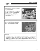
Make all adjustments with the engine shut off, spark
plug wire disconnected and mower drive disengaged.
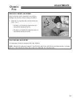
OPERATOR PRESENT CONTROL LEVERS
The operator present (OP) control levers should be
adjusted to control the operation of the plunger of the
operator present switch
B
(located under the right
side of the control panel). Depressing OP control
levers
A
should depress the plunger; releasing the
levers should extend it.
TO ADJUST:
1. Loosen clamp bolts
C
on both ends so clamps
can rotate on shaft.
2. Rotate actuator lever to depress switch plunger.
Keep OP control levers against handles and
tighten bolts
C
.
3. When released, the OP control levers
A
should
rise and the actuator lever should rotate away
from the switch, allowing the switch plunger to
extend completely.
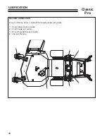
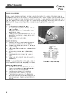
PARKING
BRAKE
POSITION
DRIVE
POSITION
NEUTRAL
POSITION
1/8”
TRACTION LOCK
TRACTION RODS AND WHEEL BELT TENSION
There should be a 1/8" minimum gap between the
traction control rod and the bottom of the drive slot
when the drive is engaged and the traction control
lever is pushed down. If there is no gap the rod will
hold the wheel belt idler up and the belt may slip. Too
much gap makes it difficult to get adequate braking
and free-wheeling neutral when traction locks are in
the neutral position. The gap may be increased from
1/8" as long as the machine will free wheel in neutral.
Increasing the gap reduces the reach to the traction
lever.
TO ADJUST
:
1. Disconnect the brake rod
R
with the traction con-
trol lever in the drive position.
2. Remove hairpin cotter from the swivel
P
on the
traction control rod
D
.
3. Lift out the rod and turn the swivel in or out obtain
a 1/4" gap on the traction control lever in the
drive position.
4. Refit the swivel to the idler bellcrank
Q
and
replace the hairpin cotter.
5. Check the gap with traction control lever pressed
down in the drive position. If it is still not 1/8",
repeat the procedure until an approximate 1/8"
gap is obtained.
6. Reconnect the brake rod. (See Traction Brake
section).
Summary of Contents for BOB-CAT 33007J
Page 5: ...5 Classic Pro LABELS ...
Page 29: ...PARTS SECTION ...
Page 42: ...42 Classic Pro FIGURE 7 PEERLESS TRANSMISSION ...
Page 44: ...44 Classic Pro 32 DECK 40 46 45 10 22 20 47 31 40 44 31 40 48 FIGURE 8 ...
Page 46: ...46 Classic Pro FIGURE 9 36 DECK 47 48 40 10 20 39 44 22 31 40 49 ...
Page 54: ...54 Classic Pro FIGURE 13 DECALS 8 4 UNDER COVER 1 12 11 7 2 10 14 6 9 15 16 13 5 3 ...


