international 75
Operation
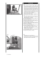
Fig. 7
1 The pressure in the tank is controlled by the pressure
switch under the pressure switch cover (2). If the set
maximum pressure is reached, the pressure switch is
activated and the motor is switched off. The pressure
will decrease in accordance with the air used by the
tool that is connected to the compressor until the set
minimum pressure is reached. The pressure switch then
turns the motor on again. The operator of the device
should keep in mind that the motor switches on and
off during operation due to the increasing and decrea-
sing pressure in the tank. The motor starts without any
previous warning.
2 The maximum and minimum pressure values were set
in the factory. These settings must not be modified.
3 All accessory parts have been connected to the adjus-
table outlet value (6).
4 The pressure of the adjustable outlet can be changed
by turning the adjustment knob as illustrated on the
adjustable outlet pressure gauge (7).
Caution: In order to be able to read out the correct output
at the output gauge, air has to flow through the outlet.
The adjustable valve must be aligned and the gauge read
out while the valve is open and the air is flowing from the
adjustable drain through the accessory part.
To increase the air pressure, turn the valve in clockwise di-
rection. To reduce the air pressure, turn the valve counter-
clockwise.
Caution: If you don’t let the air flow during the settings,
you will have an incorrect display. For a correct display,
the air has to flow.
When you have completed your work or if you leave the
compressor unattended, switch the device off as descri-
bed below:
• Press down the ON/OFF switch.
• Wait until the compressed air has been released via the
drain valve below the switch over (2).
Caution: When you press the button down you should hear
a short air release. (approx. ½ second).
Fig. 8
• Switch the machine off and pull out the mains plug.
• Pull the ring on the safety valve (8) to ensure that
the compressed air has been released from the tank
or open the drain valve of the tank in order to release
the pressure.
Summary of Contents for HC54
Page 109: ...international 107...

