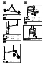
4. Installing the lower section of drum with
frame Fig.6
Set the lower section of the drum
(7)
with bear-
ing bracket
(6)
on the pre-installed framework,
tighten with 2 M8x65 hexagon bolts, 2 washers,
2 lockwashers and 2 M8 nuts.
Secure with a Ø42 spiral ring.
Secure the opposite side with a locking plate and
two M8x20 hexagon bolts.
5. Installing mixer Fig.7
Lock mixer
(9)
with 2 M10x20 cross-head screws
to the lower section of the drum with 2 washers,
2 lockwashers and 2 M10 nuts. Insert one rubber
washer each between mixer and drum.
6. Installing upper section of drum Fig.8
Place rubber ring on the lower section. Place the
upper section of drum on it.
Caution! The pasted arrows mark the exact direc-
tion of the upper or lower section of the drum.
Align the upper section of the drum and install
it on the lower section with 6 M8x16 cross-head
screws with washers and tighten. Lock mixer
(9)
with 2 M10x20 cross-head screws and 2 lock-
washers to the lower section of the drum with 2
washers, 2 lockwashers and 2 M10 nuts. Insert
one rubber washer each between mixer and
drum.
.
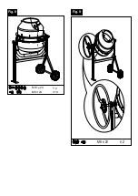
7. Installing swivel wheel. Fig. 9
Attach the swivel wheel and the ratchet disc with
two M8 hexagon bolts, washers, lock washers
and locknuts on the outside flange.
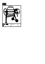
8. Installing motor casing. Fig.10
Place the motor casing on the retaining plate,
secure with 2 M8 safety nuts and flat washers.
Secure them on the frame with M8x70 hexagon
bolts.
Operation
Operate the concrete mixer only if no parts
(e.g., safety covers) are missing or defective,
and the connecting cable is not damaged.
Set up:
• Place the concrete mixer horizontally on even,
firm ground.
• Do not place it on the connecting cable!
• Route the connecting cable in a manner, such
that it cannot be kinked, crushed or damaged
in some other way.
Note:
It should be possible to swivel the drum to
the right and left. There must be sufficient
space for a wheelbarrow under the drum, so
that it can be emptied.
Activation:
• Plug the device into the socket
Activation on
“I” (green button) / Deactivation on “0” (red
button)
Moving the drum (Fig. 11):
• To move the drum, pull back the hand wheel so
that the drum can be moved.
• When the drum is in the desired position, lock
the hand wheel again.
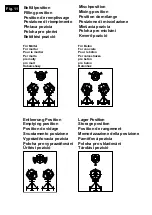
Filling
•
Before filling the drum, ensure that the opening
is aligned in such a way that the mixture cannot
fall out of the drum.
(Fig. 12)
• Put the mixture in when the drum is rotating
(do not overfill the drum)
Caution! Risk of moving parts
Emptying
• Swivel the drum in the downward direction to
empty it
• Ensure that there is an adequate container un-
der the drum (e.g., wheelbarrow).
• Ensure that no mixture falls on the ground
Transport
Caution!
Pull the power plug out, every time, before trans-
porting the machine.
1. Set the filling opening downwards.
2. During transportation by motor vehicle, re-
move the screws and fold the stands.
3. Lock the mixer with a strap to prevent displace-
ment
4. Do not lift the concrete mixer with the help of
a crane
Maintenance
Caution!
While working with the concrete mixer or per-
forming repairs on it, please do the following:
Switch off the concrete mixer, wait for the drum
to come to a standstill and pull out the power
plug
.
Repairs on the concrete mixer should be per-
formed only by authorised technicians.
Perform visual inspection before each use of the
concrete mixer.
All safety parts must be installed.
Defective connecting cables should not be used.
Service information
Please note that the following parts of this prod-
uct are subject to normal or natural wear and that
the following parts are therefore also required for
use as consumables.
Wear parts*: V-belts
* Not necessarily included in the scope of deliv-
ery!
Cleaning
Caution! Switch off the machine, wait for the
drum to come to a standstill and pull out the
power plug.
Clean the drum with water after each use of the
concrete mixer.
Remove cement and mortar residues. Do not tap
motor casing and drum with a shovel or any other
hard object, as these can be damaged.
Checking/re- adjusting belt tension
Caution! Switch off the machine, wait for the
drum to come to a standstill and pull out the
power plug.
• Remove the cover of the motor casing, check
the belt tension (on pressing the belt with the
finger, it should yield by approx. 5mm.)
• Belts are wear and tear parts that must be
replaced after a certain period. If necessary,
detach the screws on the motor, replace the
belt, adjust the correct tension and tighten the
screws again.
• Reinstall the motor cover.
17
D
GB
Summary of Contents for 5808401984
Page 4: ...4 Fig 3 Fig 4 Fig 5 Fig 6 Fig 7 M8 70 1 M6 30 2 1 1 M8 70 2 M8 20 2 M8 65 1 42 1 2 M10 20 ...
Page 5: ...Fig 8 Fig 9 2 10 M8 20 M10 20 M8 20 2 ...
Page 6: ...Fig 10 2 M8 1 M8 70 ...
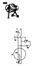
Page 8: ...WIRING DIAGRAM Fig 12 ...
Page 44: ...PARTS SCHEMATIC ...
Page 45: ......
Page 46: ......

