background image


15 

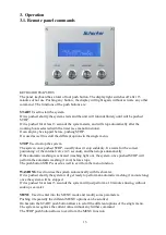
The message must be acknowledged pushing STOP. 
This messages means that an hydraulic block of the machine occurred, and then the pumps has 
been  switched off as safety procedure. In this case is suggested to perform a reset procedure and 
investigate on the possible hydraulic origins of the problem. 
If the origin of the problem is just a malfunctioning of the signal pressure switch, it is possible to  
start again the unit,  activating the bypass. 


BYPASS WARNING  
This  message  advice  or  remember  that  the  unit  is  working  in  bypass  mode  (then  some  safety 
functions are disabled).  
 
CHANGE  PUMP FILTERS 
This is a blinking messages that must be acknowledged pressing the key STOP  
This messages suggest to replace the filter of the pump group.  

 
3. Operation 
3.2. First start-up procedure  

 
The first start-up procedure is necessary to start the first time a new system,  just installed. 
The purpose of the  procedure is basically  purge out  the air from the system.  
It can be used as well after a filter replacement, or after other maintenance operations.  
Preliminary checks: 


Verify that all components are connected correctly.  


Verify that the  filters cartridges are installed.   


Verify that the seawater  valve, and the possible drain valve, are opened.  


Verify  that the reset valve is closed (lever orthogonal to the body valve) and the positioner 
completely unscrewed.  


Verify  that  the  small  gray  valve  on  the  active  carbon  filter  is  opened  and  the  fresh  water 
pump of the boat is on. 


Verify  that  the  fresh  water  tanks  are  full  enough    (at  least  50  liters)  to  perform  the  first 
washing operations.  

                                                                                                                                                                          
Start-up procedure:  
1.


Open halfway the depressurization valve (45°).   

2.


Activate the start up procedure  throw the function of the MENU (select the specific function 
in  the  menu  mode,  exit  from  menu  mode  pushing  STOP,  and  start  the  procedure  pushing 
START). 

3.


Close the depressurization valve when the display shows the specific message. 

The procedure lasts about 3 minutes. It can anyway stopped anytime pushing STOP.  
After the procedure  the system is ready to start normally.  


Summary of Contents for MODULAR 30 digital

Page 1: ...aterial required 2 2 Components mounting 2 3 Water intake 2 4 Hydraulic connections 2 5 Electric connections 3 Operating procedures 3 1 Remote panel commands 3 2 First start up procedure 3 3 Normal op...

Page 2: ...Y RECOVERY SYSTEM which amplifies the pressure of common low pressure pumps and recoups all the hydraulic energy back from the membrane This saves on the use of power allowing the Modular 60 to be run...

Page 3: ...weight 7 Kg Connections Seawater intake holder for hose int diam 16 mm Salt water outlet holder for hose int diam 16 mm Filter 5 micron polyestere pleated type Power supply 12 Vdc 20 version 30M12 24...

Page 4: ...et pressure The movement required is very small 1 4 turn 1 BAR This action will not be required in normal circumstances as the unit has been pre calibrated at the factory Before changing the settings...

Page 5: ...roduced fresh water coming out of the unit This is only indicative as the accuracy of the flowmeter is 20 Depressurization valve Is used only during the air bleeding phase at the first plant start up...

Page 6: ...protected from water It is connected to the remote panel and controls the functions of the watermaker automatically The microswitches P1and EV allow the direct command of the pump the electrovalve res...

Page 7: ...ht when the filter housing is full of water It may be necessary to create a suitable wooden or fiberglass structure for the unit if an existing one not available The base of the pump is equipped with...

Page 8: ...must be secured with double hose clamps It is not advisable to Tee into the engine cooling water intake as it may impair the cooling of the engine An easily inspected mesh type filter will be require...

Page 9: ...einforced hose An inadequate hose could burst jeopardizing seriously the safety of the boat The hydraulic connections are Low pressure max 3 bar connections sea water inlet net filter backflow valve i...

Page 10: ...rantee a water head PRODUCTION FRESH WATER CONNECTION The connection has to be made using the small hose supplied with the equipment The connection has to be made between the polyethylene pipe that co...

Page 11: ...able below Voltage Automatic Cable lenght switch up to 3 mts 3 7 mt 7 10 mt Volt Ampere mm2 AVG mm2 AVG mm2 AVG 12 16 4 11 10 7 16 5 24 10 2 5 13 4 11 4 11 Electric cables and switches selection table...

Page 12: ...12 Wiring connection diagram Signal pressure switch Electrovalve...

Page 13: ...uddenly It awaits for the correct positioning of the internal valve 2 3 seconds and then stops automatically If the automatic washing is activated washing light on the system once pushed STOP will per...

Page 14: ...cartridge replacement or a general service The procedure allows to purge completely the air from the system and from the seawater and the washing fresh water hoses The depressurization valve must be...

Page 15: ...rge out the air from the system It can be used as well after a filter replacement or after other maintenance operations Preliminary checks Verify that all components are connected correctly Verify tha...

Page 16: ...row the specific timer menu the system will hold as well the previous setting Push the button START for more than 3 seconds The display will show the decreasing production time The system will stop af...

Page 17: ...n to jam again resulting in a typical start stop noise After approx 20 sec the computer recognize the problem and turn off the pumps and the message WARNING SYSTEM BLOCKED is displayed This event besi...

Page 18: ...efully following the indications on the pack Wear a protection mask in order to avoid inhaling product dusts The water temperature doesn t have to be lower than 25 C preferably 3 Close the grey valve...

Page 19: ...e the filter holder Active carbon filter replacement Every 6 months Close the grey valve before open the filter Purge periodically the air from the system opening at 45 for a couple of minutes the dep...

Page 20: ...5 Bar Cold sea water Filter clogged Dirty membranes Normal operation Clean filter Perform cleaning cycle Leaking in the plant Loose connectors ERS loss Tighten connectors Contact a service point Prob...

Page 21: ...S Unless the correct cleaning procedures are carried out in accordance with this manual there may be bacteria present in the produced water Therefore avoid drinking the water produced by the plant if...

Page 22: ...Service Point or our factory will be on customer account The under guarantee delivered parts transport will be at customer s own risk In case of repairs under guarantee directly performed by our techn...

Reviews: