SCHEMPP-HIRTH FLUGZEUGBAU GmbH., KIRCHHEIM/TECK
Ventus-2cM
FLIGHT MANUAL
7.12 Electrical system
Gliding avionics
When operated in the plane sailplane configuration, the minimum instrumentation
prescribed does not require an electrical power source.
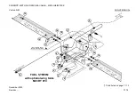
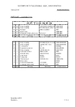
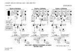
Additional equipment is to be wired as shown on page 7.12.2 and must comply
with the manufacturer’s instruction of the relevant instrument.
Power for the avionics is supplied by one or more batteries located as follows:
•
Upper end of fin (option)
•
R.h.s. of main wheel housing (option)
•
Base of instrument pane
Using a selector switch, power may also be provided by the power plant battery.
A main switch controls the power sources for power plant a n d gliding avionics.
Power plant
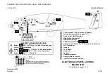
The engine features a dual-ignition system by means of magnetos (contactless)
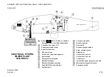
and a generator charging the12 V power plant batteries. The latter, situated in the
fuselage nose as shown on page 7.12.3 “ELECTRICAL SYSTEM – POWER
PLANT”, are only necessary for operating pylon spindle drive, starter motor and
ILEC control unit (with RPM indicator).
The power plant batteries are controlled by a circuit breaker (50 A), their voltage is
displayed by the ILEC control unit. By using a selector switch, power may also
feed the gliding avionics.
The power plant batteries are recharged by an AC generator via a rectifier re-
gulator, however, they may also be charged from an external power source via
a charger socket provided in the console at the base of the instrument panel.
With power plant master switch “ON” (50 A circuit breaker), various signals and
values may be obtained from the ILEC control unit.
A description of this unit’s various functions and of all other power plant control
elements including their interconnections is given in section 7.3.
November
2003
Revision --
7.12.1
Summary of Contents for Ventus-2cM
Page 11: ......

