


ELECTRICAL ADJUSTMENTS
D3-2
(TV SECTION)
2-4: CONSTANT VOLTAGE
1.
2.
3.
4.
Connect the digital voltmeter to TP501.
Set condition is AV MODE without signal.
Using the remote control, set the brightness and
contrast to normal position.
Adjust the VR502 until the digital voltmeter is 135
±
1V.
2-5: FOCUS
1.
2.
3.
Receive the monoscope pattern.
Turn the Focus Volume fully counterclockwise once.
Adjust the Focus Volume until picture is distinct.
2-6: HORIZONTAL POSITION
1.
2.
3.
4.
5.
Receive the center cross signal from the Pattern
Generator.
Using the remote control, set the brightness and
contrast to normal position.
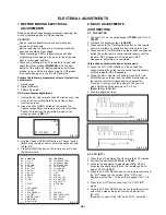
Activate the adjustment mode display of Fig. 1-1 and
press the channel button (08) on the remote control to
select "H POSI (50)".
Press the VOL. UP/DOWN button on the remote
control until the right and left screen size of the
vertical line becomes the same.
Receive the cross hatch signal of NTSC. Then perform
the above adjustments 2~4.
NOTE: Adjust after performing adjustments in section 2-8.
2-9: VERTICAL SIZE
Receive the cross hatch signal from the Pattern
Generator.
Using the remote control, set the brightness and
contrast to normal position.
Activate the adjustment mode display of Fig. 1-1 and
press the channel button (11) on the remote control to
select "V SIZE (50)".
Press the VOL. UP/DOWN button on the remote control
until the rectangle on the center of the screen becomes
square.
Receive a broadcast and check if the picture is normal.
Receive the cross hatch signal of NTSC. Then perform
the above adjustments 2~4.
1.
2.
3.
4.
5.
6.
2-3: RF AGC
1.
2.
3.
4.
5.
Place the set with Aging Test for more than 15 minutes.
Receive the VHF HIGH (63
±
2dB).
Connect the digital voltmeter between the pin 5 of
CP603 and the pin 1 (GND) of CP603.
Activate the adjustment mode display of Fig. 1-1 and
press the channel button (01) on the remote control to
select "RF AGC".
Press the F.FWD, REW button on the remote control
until the digital voltmeter is 2.4
±
0.05V.
2-8: VERTICAL LINEARITY
NOTE: Adjust after performing adjustments in section 2-7.
1.
2.
3.
Receive the cross hatch signal from the Pattern
Generator.
Using the remote control, set the brightness and contrast
to normal position.
Adjust the VR401 until the SHIFT quantity of the OVER
SCAN on upside and downside becomes minimum.
2-7: VERITCAL POSITION
2-10: OSD HORIZONTAL
1.
2.
3.
Using the remote control, set the brightness and
contrast to normal position.
Activate the adjustment mode display of Fig. 1-1 and
press the channel button (31) on the remote control to
select "H POS OSD".
Press the VOL. UP/DOWN button on the remote control
until the difference of A and B becomes minimum. (Refer
to Fig. 2-2)
H POS OSD 41
A
B
Fig. 2-2
( PAL)
TV
2-11: CUT OFF
1.
2.
3.
4.
5.
Set condition is AV MODE without signal.
Using the remote control, set the brightness and contrast
to normal position.
Place the set with Aging Test for more than 15 minutes.
Activate the adjustment mode display of Fig. 1-1 and
press the channel button (00) on the remote control to
select "CUT OFF".
Adjust the Screen Volume until a dim raster is obtained.
NOTE: Adjust after performing adjustments in section 2-6.
Receive the cross hatch signal from the Pattern
Generator.
Using the remote control, set the brightness and
contrast to normal position.
Activate the adjustment mode display of Fig. 1-1 and
press the channel button (09) on the remote control to
select "V POSI (50)".
Check if the step No. V.POSI (50) is "5".
Adjust the VR402 until the horizontal line becomes fit to
notch of the shadow mask.
Receive the cross hatch signal of NTSC. Then perform
the above adjustments 2~4.
Check if the step No. V.POSI (60) is "8".
1.
2.
3.
4.
5.
6.
7.