


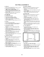


ELECTRICAL ADJUSTMENTS
D3-1
2. BASIC ADJUSTMENTS
(VCR SECTION)
2-1: PG SHIFTER
1.
2.
3.
4.
Connect CH-1 on the oscilloscope to TP4001 and CH-2 to
TP4201.
Playback the alignment tape. (JG001E)
Press and hold the Tracking-Auto button on the remote
control more than 2 seconds to set tracking to center.
Press the VOL. DOWN button on the set and the channel
button (3) on the remote control simultaneously until the
indicator REC disappears. If the indicator REC
disappears, adjustment is completed.
(If the above adjustments doesn't work well:)
5.
6.
7.
Press the VOL. DOWN button on the set and the
channel button (3) on the remote control simultaneously
until the indicator REC disappears.
When the REC indicator is blinking, press both VOL.
DOWN button on the set and the channel button (4) on
the remote control simultaneously and adjust the
Tr/- button until the arising to the down of
Head Switching Pulse becomes 6.5
±
0.5H.
(Refer to Fig. 2-1-A, B)
Stop the alignment tape.
CH-1
CH-2
6.5H
Fig. 2-1-A
CH-2
CH-1
6.5H
Fig. 2-1-B
2-2: VCO (AFT)
1.
2.
3.
4.
5.
6.
Place the set with Aging Test for more than 10 minutes.
Connect the oscillator (38.9MHz) to TP601.
Activate the adjustment mode display of Fig. 1-1 and
press the channel button (13) on the remote control to
select "VCO COARSE".
Press the F.FWD, REW button on the remote control until
the "OK" appear on the screen. If the "OK" is not
displayed, select the "-" side on the changed from "+" to
"-".
Press the CH UP button once to set to "VCO FINE"
mode.
Press the F.FWD, REW button on the remote control to
select the 2 step down point from the upper limit on
the "OK".
(Example: In case of the "OK" point 30~41, select 36.)
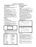
1. BEFORE MAKING ELECTRICAL
ADJUSTMENTS
Read and perform these adjustments when repairing the
circuit or replacing parts or PCB assemblies.
CAUTION
Use an isolation transformer when performing any
service on this chassis.
Before removing the anode cap, discharge electricity
because it contains high voltage.
When removing a PCB or related component, after
unfastening or changing a wire, be sure to put the wire
back in this original position.
When you exchange IC and Transistor for a heat sink,
apply the silicon grease (YG6260M) on the contract
section of the heat sink, Before applying new silicon
grease, remove all the old silicon grease. (Old grease
may cause damages to the IC and Transistor.)
•
•
•
•
Fig. 1-1
On-Screen Display Adjustment
1.
2.
Unplug the AC plug for more than 30 minutes to set the
clock to the non-setting state. Then, set the volume
level to monimum.
Press the VOL. DOWN button on the set and the
Channel button (9) on the remote control for more than
2 seconds to appear the adjustment mode on the
screen as show in FIG. 1-1.
Prepare the following measurement tools for electrical
adjustments.
1.
2.
3.
Oscilloscope
Digital Voltmeter
Pattern Generator
01 RF AGC 27
( PAL)
TV
3.
4.
Use the Channel UP/DOWN button or Channel button
(0-9) on the remote control to select the options shown
in Fig. 1-2.
Press the MENU button on the remote control to end
the adjustments.
Fig. 1-2
FUNCTION
CUT OFF
RF AGC
AGC GAIN
R DRIVE
R CUTOFF
G DRIVE
G CUTOFF
B DRIVE
H POSI
V POSI
---
V SIZE
---
VCO COARSE
VCO FINE
VCO COARSE L1
VCO FINE
L1BRIGHT CENT
BRIGHT MAX
BRIGHT MIN
NO.
00
01
02
03
04
05
06
07
08
09
10
11
12
13
14
15
16
17
18
19
FUNCTION
CONTRAST CENT
CONTRAST MAX
CONTRAST MIN
COLOR CENT
COLOR MAX
COLOR MIN
TINT
SHARP
M R CUT OFF
M G CUT OFF
M B CUT OFF
H POS OSD
---
---
---
CVBS OUT
APR THRESHOLD
BELL FILTER
BANDPASS
NO.
20
21
22
23
24
25
26
27
28
29
30
31
32
33
34
35
36
37
38