


DISASSEMBLY INSTRUCTIONS
Fig. 1-5
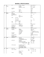
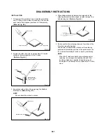
1-5: DECK SHIELD PLATE (Refer to Fig. 1-5)
1.
2.
3.
4.
Remove the 3 screws (1).
Remove the Deck Shield Plate in the direction of arrow (A).
Remove the screw (2).
Remove the Bottom Shield Plate in the direction of arrow (B).
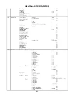
Syscon PCB
Deck Holder
Fig. 1-7
1.
2.
3.
Remove the screw (1).
Remove the 2 screws (2).
Remove the Syscon PCB in the direction of arrow.
1-7: JACK PLATE AND SYSCON PCB (Refer to Fig. 1-7)
B1-2
Deck Shield Plate
TV/VCR Block
(B)
(A)
Bottom Shield Plate
(1)
(1)
(2)
(2)
(2)
(1)
(1)
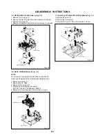
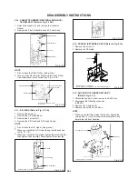
1-6: DECK CHASSIS (Refer to Fig. 1-6)
NOTE
Do not remove the cable at the FE Head section. The FE
Head may be damaged if you remove the cable by force.
1.
2.
3.
4.
5.
Remove the screw (1).
Remove the FE Head.
Remove the 2 screws (2).
Disconnect the following connectors:
(CP1001, CP4001, CP4004 and CP4005).
Remove the Deck Chassis in the direction of arrow.
Deck Chassis
Syscon PCB
Fig. 1-6
(1)
(2)
(2)
FE Head