4
to the fan casing to facilitate work on
the terminal box (fig. 6).
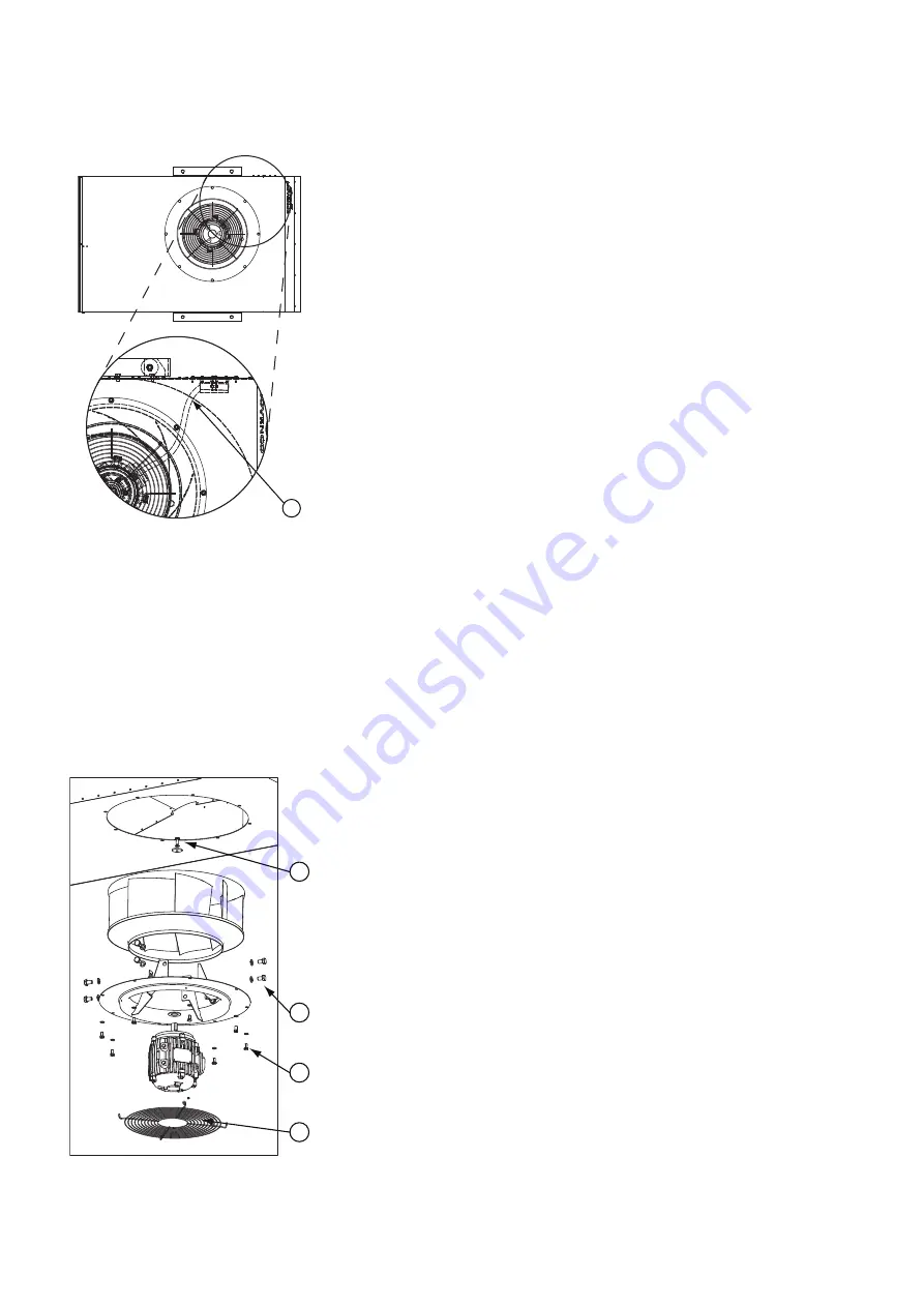
3 Disconnect the motor cable in the
terminal box and loosen the internal
cable connector (fig. 7, pos. 1) at the
separation from the pressure
chamber. Push the cable fully into the
pressure chamber.
4 Prepare support of the motor
arrangement, e.g., with a lift, in order
to lift it as short as possible and
preferably straight down.
5 Loosen the motor arrangement (eight
M8x16) (fig. 8, pos. 1) from the fan
casing and take it down.
The arrangement requires two people
to take down safely. Make sure to pull
the motor cable completely free of the
fan casing.
6 Leave the wire guard affixed to the
inlet nozzle (fig. 8, pos. 2).
7 Remove the impeller by removing the
motor shaft screw (fig. 8, pos. 3).
8 Disconnect the motor from the inlet
nozzle. It is attached with eight 12x20
screws (fig. 8, pos. 4).
9 Slide the steel tube off the motor cable.
The motor is now ready for service. Refer
to the motor supplier’s instructions for
service.
7.7 Assembly of motor
Lubricate bolts with grease, before
screwing them in during re-assembly.
Assembly procedure
1 Slide the steel tube onto the cables for
the new motor.
2 Affix the motor to the inlet nozzle
with the eight 12x20 screws (fig. 8,
pos. 4).
3 Install the impeller on the inlet nozzle
and attach to motor shaft.
4 If the wire guard has been removed,
then this is affixed to the inlet nozzle
with four blind rivets 3.2x10 of
stainless steel grade A2 (fig. 8, pos. 2).
5 Support and place the motor
arrangement in the fan casing. Make
sure to pull the motor cable along the
same route as was done from the
factory.
The arrangement is attached with
eight M8x16 screws (fig. 8, pos. 1).
6 Roll the motor cable up into the
terminal box room before tightening
the connector at the separation from
the pressure chamber.
7 Connect the motor cable in the
terminal box and install it and the
cover (fig. 6).
8 Tighten the external motor cable
connector.
9 Connect the power supply for the fan
and follow the procedure for startup
in section “6.2 Start procedure”.
7.8 Troubleshooting
The following are possible causes of
breakdowns and failures.
Poor performance
• The inlet or the outlet side of the fan
is blocked.
• Motor defect
• Motor disconnected
• Faulty electrical connection
• Wrong direction of rotation
Noise/vibrations
• Faulty bearings in motor
• Impeller imbalance
• Wear/damage to impeller
• Loose screws/components
• Fan operates in stall condition, which
may lead to damage. Correct faults -
see “Poor performance”.
• Aged or ruptured vibration dampers
8. Inspection and test
It is recommended to test and inspect the
CGF fans at regular intervals with regard
to operability and operating conditions.
Extent of inspection
• Measure power consumption at high
and low speeds
• Check torques for fixing bolts and
correct if necessary
• Vibration measurement on fan casing
(next to motor)
• Visual inspection of impeller, fan
casing, vibration dampers, and
electrical connection
• Cleaning
– inside with a wet cloth, pressurised
air or vacuum cleaning
– outside with water - avoid water in
the electrical systems
Enter all values and observations in a
log.
Figure 7.
Loosen internal connector
Figure 8.
Disassembly of motor
1
2
1
4
3


