Fire-resistant damper model BKA-Ü
Technical documentation
Installation in lightweight partition walls with metal posts
Construction subject to change
No return possible
Version: 2021-07-01 | Page 22
LIGHTWEIGHT PARTITION WALLS (F30/F60) WITH
PANELLING ON BOTH SIDES AND WALL
THICKNESS W ≥ 75 MM
Installation in lightweight partition walls with metal posts
and panelling on both sides (gypsum-bonded wall boards;
wall thickness
≥
75 mm) according to classification to EN
13501-2 or comparable national standards.
Installation and mounting aids on site must be removed.
Dry installation of the damper
The dry installation must be carried out during the assembly
of the wall.
The minimum distance of BKA-Ü from one another must be
at least 200 mm.
The minimum distance to adjacent components is at least
80 mm from the ceiling and at least 90 mm from the wall.
The actual minimum distance may slightly differ from the
distances mentioned therein and must be executed and
adapted as a function of the wall connection type.
Further information to be considered: see page 7 Minimum
distances or projecting ends.
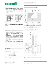
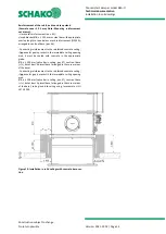
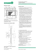
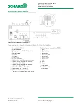
Figure 33: Metal post with required exchange parts for dry
installation (F30/F60)
Mounting information:
In the overlap area of the exchangeable profiles, they must
be riveted, crimped or screwed once on both sides. These
connections are only for fastening the individual metal pro-
files during mounting.
Installation procedure
Mount the metal posts and the wall in accordance with the
specifications of the wall manufacturer and the required ex-
change parts as shown on Figure 33.
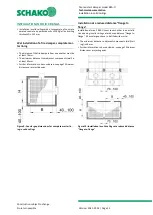
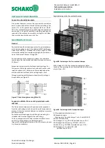
Insert BKA-Ü (pos. 1) into the wall recess (operating side -
observe the installation dimension of 210 mm). Average out
the circumferential annular gap evenly between the wall
and BKA-Ü. Mounting of BKA-Ü with the help of mounting
suspensions etc.
Insert mineral wool (pos. 11.4) into the circumferential gap
40 mm in width between the BKA-Ü housing and the circum-
ferential metal profiles (pos. 10).
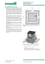
Mount the wall panellings on both sides (pos. 12) and the
doublings on the non-operating side (pos. 49.4). The con-
nection and butt joints must be filled with the jointing ma-
terial of the wall (pos. 43; max. gap width 5 mm, perform
jointing operation as part of assembly).
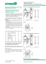
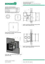
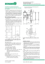
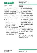
Detail Q
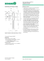
Figure 34: Wall panelling and double-board layers (light-
weight partition wall)
1 Fire-resistant damper model BKA-Ü
9 Profile CW 50/50/06
10 Profile UW 50/40/06
11.1 Mineral wool, according to the wall manufacturer's
specifications
11.4 Mineral wool, (non-flammable according to EN 13501-1,
apparent density approx.
30 kg/m³, melting point ≥ 1000
°C, thickness 40 mm)
12 Panelling (on both sides) of the metal stud wall made of
gypsum-bonded wall boards
16 Solid ceiling
43 Joint filling with jointing material of the wall
48 Thermal insulation
49.4 Doubling (plaster boards GKF, 2 x d=12.5 mm)
•
First doubling, fastening: Dry-wall screws, for example,
TN 3.5x55, a ≤ 250 mm, or at least 2 screws per side,
connection or butt joints of the doubling must be filled
with the jointing material of the wall.
•
Second doubling, fastening: dry-wall screws e.g.
ø3.9x55, a
≤
250 mm, but at least 2 screws per side,
connection and butt joints of the doublings must be
filled with the jointing material of the wall.


