background image

7


PART#-31600075 LIT-SDD4000-HVAC-S INSTALL REV.A

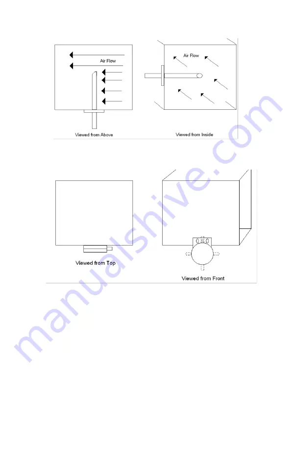
4.  Secure the probe to the duct with the provided #6 x 3/8” sheet metal screws.

5.  In a location close to the probe attach the pressure switch in a vertical orientation. Bend 

mounting bracket as needed to attain vertical positioning. 

6.  Connect the pressure sensor to the duct probe with the clear ¼” ID x 3/8” OD tubing 

provided.

7.  Attach the two press-on connectors at one end of the 25 foot 18 gauge wire provided 

to the tabs on the pressure sensor in either order.  

8.  The cable from the sensor switch will be connected to the screw terminal connector on 

top of the modified SDD4004. Connect like colors together at the connector (the red 
wire on the cable to the side of the connector with the red wire from the machine) and 
tighten securely with a fine slotted screwdriver.

9.  IMPORTANT: Check that the “HVAC“icon on the 4004 display is shown when the HVAC 

fan is on, and goes out when the Fan turns off.  (if you are unable to switch the HVAC 
off, temporarily disconnect the clear plastic tubing between the sensor probe and the 
sensor switch to verify proper sensor operation). If the sensor (Part #9) is installed at 
an angle off of vertical or is subject to vibration it will not properly report changes in 
airflow. If it seems to always be indicating ON or OFF double check the installation 
angle while observing the 4004 display.

10.  Set up schedules on the SDD4004 machine as per the manual to establish scent event 

times, intensities and other settings.

Summary of Contents for ScentDirect HVAC-S

Page 1: ...rately PARTS INCLUDED 1 PVDF Tubing 6 x OD x 17 ID 30200189 x 6 both ends sealed 2 HVAC Adapter Cap 30400032 3 4x Self Tapping Screws 12x1 30210304 4 Duct Mount Assembly 5 3 Zip Tie 30217001 6 Replace...

Page 2: ...located Fasten the screw terminal connector to the machine with the screw Part 7 from the kit FIG 1 4 Unlatch and open the door of the SDD4004 system to access the control panel 5 Use the 2 Phillips s...

Page 3: ...the PCB box through the hole at the rear along with the other wire connectors Feed the wires through the slot in the fan housing FIG 2 11 Pass the wires up and out through the slot shown in the top o...

Page 4: ...wires are connected to the 2 pins on the control board The 3 pin connector on the control board will be left unused 15 Reattach PCB faceplate assembly to SDD4004 and secure with the 4 flathead screws...

Page 5: ...ing through DUCT MOUNT as shown FIG 4 6 Secure the tubing to the Duct Mount as shown using zip ties The opening must be just past the end of the metal rod and the tubing must be secure to allow the ro...

Page 6: ...itch 2 Find a location at least 5 times the diameter downstream from any elbows obstructions fans or any significant change in duct area For a round duct with a 10 diameter the insertion point needs t...

Page 7: ...together at the connector the red wire on the cable to the side of the connector with the red wire from the machine and tighten securely with a fine slotted screwdriver 9 IMPORTANT Check that the HVA...

Page 8: ...For further assistance please contact ScentAir Technical Services North America 1 704 504 2320 Europe 33 0 5 62 57 63 20 Asia 852 356 378 42 techservices scentair com...

Reviews: