


7
R
Section 2
1. To lower the roll bar, lower the rear cover at the back
of the machine. See Figure 2-1.
2. Remove the hairpin cotter pins and remove the two
(2) lock pins. See Figure 2-1.
3. Lower the roll bar to the folded position and close the
rear cover. See Figure 2-1.
4. To raise the roll bar, lower the rear cover and lift the
bar to the upright position.
5. Install the two (2) lock pins through the holes, secure
with the two (2) hairpin cotter pins and close the rear
cover. See Figure 2-1.
FOLDED
POSITION
UPRIGHT AND
LOCKED POSITION
HAIR PIN
LOCK PIN
Figure 2-1. Foldable Roll-Over Protection System
5
o
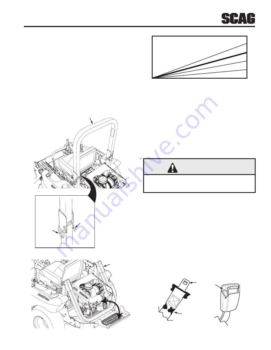
10
o
15
o
20
o
Figure 2-2. Slope Angle Graph
The potential exposure of the seat belt to severe
environmental conditions makes it crucial to inspect the
seat belt system regularly.
It is recommended that the seat belt be inspected on a
daily basis for signs of damage. Any seat belt system
that shows cuts, fraying, extreme or unusual wear,
significant discoloration due to UV exposure, dirt or
stiffness, abrasion to the seat belt webbing, or damage
to the buckle, latch plate, hardware or any other obvious
problem should be replaced immediately.
WARNING
Failure to properly inspect and maintain the seat
belt can cause serious injury or loss of life.
1. Check the full length of the seat belt webbing for
cuts, wear, fraying, dirt and stiffness. See Figure 2-3.
2. Check the seat belt webbing in areas exposed to
ultra violet rays from the sun or extreme dust or
dirt. If the original color of the webbing in these
areas is extremely faded and/or is packed with dirt,
the physical strength of this webbing may have
deteriorated. If this condition exists, replace the seat
belt system.
3. Check the buckle and latch for proper operation
and determine if the latch plate is excessively worn,
deformed, or if the buckle is damaged or cracked.
See Figure 2-3.
INSPECT WEBBING
INSPECT BUCKLE
& LATCH
Figure 2-3. Seat Belt Inspection


