Quanta series
– Hardware Manual
QUANTAHM.1.2
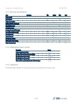
4.3. Electrical specifications
4.3.1. Connector specification
Connectors
Manufacturer
Manufacturer P/N
Description
IMU connector
NICOMATIC
221V10F25
Connector, Board mounted, Horizontal,10 pin contacts, M2 screws assembly
Mating Connector
NICOMATIC
202S10
Connector, Male, 10cts, 2mm pitch, Jackscrews, Straight, 24-28 AWG conductors
Mating Connector
NICOMATIC
202C10
Connector, Male, 10cts, 2mm pitch, Jackscrews, Straight, 22 AWG conductors
Mating Connector
HARWIN
M80-4811005
Connector, Male, 10cts, 2mm pitch, Jackscrews, Straight, 24-28 AWG conductors
Mating Connector
HARWIN
M80-4801005
Connector, Male, 10cts, 2mm pitch, Jackscrews, Straight, 22 AWG conductors
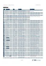
4.3.2. Pin-out
Pin Name
Type
Description
Connection Tips
1
VDD
Power Input
Power Supply Input, isolated from other signals
2
TX- / B
RS422 Output
RS485 I/O
RS422: Data Transmit Output Signal (- differential)
RS485: Data Transmit/Receive (– differential)
RS422: Add a 120Ω termination resistor near
receiver
RS485: Internal 120Ω termination included
3
RX-
RS422 input
Data Receive Signal (- differential)
120Ohm termination resistor included
4
SYNC_OUT-
RS422 Output Synchronization Input Signal (- differential),
Add a 120Ω termination resistor near receiver
5
RS422 / RS485 RS232 Input
RS422 / RS485 interface mode selection pin
Leave unconnected to select RS422 mode.
Tie to SGND to select RS485 mode
6
VSS
Power Return Power Supply Return, isolated from other signals
7
TX+ / A
RS422 Output
RS485 I/O
RS422: Data Transmit Output Signal (+
differential)
RS485: Data Transmit/Receive (+ differential)
Add a 120Ω termination resistor near receiver
RS485: Internal 120Ω termination included
8
RX+
RS422 input
Data Receive Signal (+ differential)
120Ohm termination resistor included
9
S
RS422 Output Synchronization Input Signal (+ differential),
Add a 120Ω termination resistor near the
receiver
10
SGND
I/O
Signal Reference for TX/RX and Sync Out
differential pairs
25/48


