Quanta series
– Hardware Manual
QUANTAHM.1.2
3.3.2. External IMU connector
3.3.2.1. Type
Connectors
Manufacturer
Manufacturer P/N
Description
Processing Micro-Module
NICOMATIC
201T10L
Connector, Datamate L-Tek serie, Male, Vertical, 10 cts, 2.2A,
2mm pitch, SMD
Mating board Connector
HARWIN
M80-8881005
Connector, Datamate L-Tek serie, Female, 10 cts, 24-28 AWG,
2mm pitch, Cable Mount
Mating board Connector
HARWIN
M80-8891005
Connector, Datamate L-Tek serie, Female, 10 cts, 22 AWG,
2mm pitch, Cable Mount
Mating board Connector
NICOMATIC
202C10
Connector, CMM200 serie, Female, 10 cts, 22 AWG, 2mm pitch,
Cable Mount
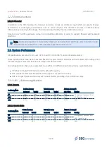
3.3.2.2. Pin-out
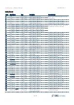
Pin # Signal Name
Type
Description
Connection tips
1
VDD_EXT_IMU
Power
Output
Power Supply Output for remote IMU, 300mA
capability
2
PORT_IMU_RX-
Input
Port IMU Data Receive Input Signal (-), features
120Ohm termination resistor
3
PORT_IMU_TX-
Output
Port IMU Data Transmit Output Signal (-)
Place a 120Ohm termination resistor near
the receiver
4
PORT_IMU_SYNC_IN-
Input
IMU Synchronization Input Signal (-), features
120Ohm termination resistor
5
GND
Ground
Signal Voltage Reference
Pins 5, 6 and 10 connected together. Use
at least one pin for ground connection.
6
GND
Ground
Signal Voltage Reference
7
PORT_IMU_RX-
Input
Port IMU Data Receive Signal (+), features
120Ohm termination resistor
8
PORT
Output
Port IMU Data Transmit Signal (+)
Place a 120Ohm termination resistor near
the receiver
9
PORT_IMU_
Input
Port IMU Synchronization Input Signal (+),
features 120Ohm termination resistor
10
GND
Ground
Signal Voltage Reference
Pins 5, 6 and 10 connected together. Use
at least one pin for ground connection.
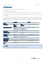
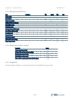
3.3.2.3. Electrical specifications
Item
Conditions
Min
Typical
Max
Unit
Power supply
Output voltage
12
V
Max output current
300
mA
RS-422 Receivers / SYNC IN
Receiver Common Mode range
-7
12
V
Input differential threshold
-200
-125
-50
mV
Input hysteresis
25
mV
18/48

