background image

Navsight Solution 

– Hardware Manual  

NAVSIGHTHM.1.5

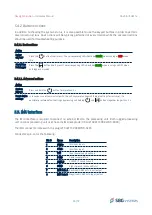
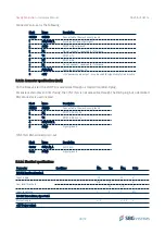
5.4. Keyboard and LEDs indicators

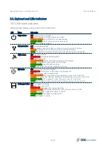
5.4.1. LEDs status indicators

Following LEDs display various useful status information.

LED

Name

Color codes

Power status

OFF: No power supply available

RED

: Unit is Idle (not running but power is available).

BLINKING ORANGE

: No valid IMU data has been received

BLINKING GREEN

: Unit is starting up and is not yet ready

GREEN

: Unit is running correctly

Ethernet status

OFF: No network connected

RED

: The product wasn't able to get a valid auto ip (private) or static IP address

ORANGE

: The product has a valid auto ip (private) or static IP address

GREEN

: The product has successfully obtained a valid IP address from a DHCP server

GNSS status

OFF: No GNSS available

BLINKING RED:  

Unknown positioning mode

RED

: Standalone mode

BLINKING ORANGE

: DGNSS with RTCM data older than 10 seconds

ORANGE

: Stable DGNSS mode with optimal RTCM age

BLINKING GREEN

: Float RTK or PPP solution

GREEN

: Fixed RTK or PPP solution (centimetric accuracy)

INS status

OFF: Kalman filter is not yet initialized

BLINKING


RED

: Vertical gyro / AHRS mode in alignment phase

RED

: Vertical gyro / AHRS in aligned mode

BLINKING ORANGE

: INS, in alignment phase. INS outputs are not all in "valid state"

ORANGE

: INS is aligned but Position/Velocity/Attitude/Heading are not all in "valid state"

BLINKING GREEN

: INS, in alignment mode. INS outputs are all in "valid state"

GREEN

: INS, is aligned and Position/Velocity/Attitude/Heading are all in "valid state"

Datalogger status OFF: Datalogger not running

RED

: Datalogger error or full

BLINKING RED

: Data logger disk is being formatted

BLINKING ORANGE

: Data logger is waiting for data but disk is almost full > 80%

ORANGE

: Data logger is logging but almost full >80%

BLINKING GREEN

: Data logger is waiting for data

GREEN

: Data logger is running

34/73

Summary of Contents for Navsight

Page 1: ...tion Inertial Systems for Survey Applications Hardware Manual Document NAVSIGHTHM 1 5 Revision 1 5 Nov 30 2022 Support EMEA support sbg systems com 33 1 80 88 43 70 Americas support sbg systems com 1...

Page 2: ...ter NAVDOC 31 Added Asterx m3 specifications 1 3 Jul 2 2020 Alexis Guinamard NAVDOC 18 Update heading performance for FW 3 0 NAVDOC 16 Updated data logger LED documentation NAVDOC 15 Updated PPP Corre...

Page 3: ...9 2 3 2 1 Mechanical specifications 19 2 3 3 Internal GNSS Septentrio Asterx 4 HW Revision 2 1 20 2 3 4 Internal GNSS Septentrio Asterx m3 HW Revision 2 1 21 2 3 5 Internal GNSS Trimble HW revision 1...

Page 4: ...ications 38 5 8 Serial ports interfaces 39 5 8 1 PORT A Interface 39 5 8 1 1 SYNC Out A functionality 39 5 8 1 2 Connector specifications rugged 39 5 8 1 3 Connector specifications rack 40 5 8 1 4 Ele...

Page 5: ...ort 54 6 4 Warranty liability and return procedure 54 7 Appendix A Ordering codes and Accessories 55 7 1 Ekinox IMU Ordering codes 55 7 2 Apogee IMU Ordering codes 55 7 3 Horizon IMU Ordering code 55...

Page 6: ...3 4 Bottom view 66 8 4 Apogee IMU Subsea enclosure 67 8 4 1 Top and bottom views 67 8 4 2 Front view 67 8 5 Horizon IMU 68 8 5 1 Top view 68 8 5 2 Right view 68 8 5 3 Front view 69 8 5 4 Bottom view 6...

Page 7: ...otocol Ingress Protection LNA Low Noise Amplifier MEMS Micro Electro Mechanical Systems MRU Motion Reference Unit MTBF Mean Time Between Failures NA Not applicable NMEA NMEA 0183 National Marine Elect...

Page 8: ...antenna triple frequency GNSS receiver optional capable of PPP and centimetre precision using RTK and all inputs and outputs interfaces In addition to the standard Inertial Navigation System outputs...

Page 9: ...es low noise gyroscopes The integrated accelerometers are ultra low noise and highly efficient in vibrating environments due to a low Vibration Rectification Error Sensor specifications are listed bel...

Page 10: ...prolonged operation in salt water environments Check section Maintenance for more details about operation in sea water environments The table below summarizes all mechanical and environmental specifi...

Page 11: ...h two taper pins 4 mm h7 a yaw alignment better than 0 04 Origin of measurements The Ekinox IMU offers the possibility to output data at different measurement points The default center of measurement...

Page 12: ...ordinate frame center drawing It is represented on the mechanical outlines by the symbol This point is defined to simplify installation Alternatively user can select between two other center of measur...

Page 13: ...bias instability hr 0 05 Allan variance 25 C Angular Random Walk hr 0 012 Allan variance 25 C Bandwidth Hz 100 Attenuation of 3 dB Orthogonality 0 02 Over temperature range 2 2 2 3 Surface form facto...

Page 14: ...stallation Alternatively user can select between two other center of measurement points Alignment hole aligned to the bottom of the base plate Bare IMU center of measurement represented by the symbol...

Page 15: ...ent is located on top of Apogee enclosure on the coordinate frame center drawing It is represented on the mechanical outlines by the symbol It is defined to simplify installation Alternatively user ca...

Page 16: ...The Horizon IMU enclosure is composed of two anodized aluminum parts 6061 one for the cover and one for the base plate The device uses high quality alloys and connectors to offer a full IP 68 enclosur...

Page 17: ...ns The table below summarizes all mechanical and environmental specifications Electrical and Mechanical Specifications Enclosure materials Anodized Aluminum 6061 Dimensions 15 x 16 8 x 21 5 cm Weight...

Page 18: ...cessing unit Interfaces specifications for more details about processing unit connectors and interfaces 2 3 1 1 Mechanical specifications The table below summarizes all mechanical and environmental sp...

Page 19: ...ut processing unit connectors and interfaces 2 3 2 1 Mechanical specifications The table below summarizes all mechanical and environmental specifications Electrical and Mechanical Specifications Enclo...

Page 20: ...SS outage This receiver provides best accuracy and reliability in harsh GNSS environments thanks to a very advanced auto mitigating algorithm that detects and eliminates multi path situations or Inmar...

Page 21: ...GPS outage This receiver provides best accuracy and reliability in harsh GNSS environments thanks to a very advanced auto mitigating algorithm that detects and eliminates multi path situations or Inma...

Page 22: ...iver provides excellent accuracy and reliability in harsh GNSS environments Specification Remark Channels 336 Signal tracking GPS L1 C A L2E L2C L5 GLONASS L1 C A L2 C A L3 CDMA Galileo E1 E5A E5B E5A...

Page 23: ...er provides excellent accuracy and reliability in harsh GNSS environments Specification Remark Channels 220 Signal tracking GPS L1 C A L2E L2C L5 GLONASS L1 C A L2 C A L2 P L3 CDMA Galileo E1 BOC E5A...

Page 24: ...a typical 1 cm accuracy position PP Post Processed data using Qinertia with at least Precise Point Positioning data 3 1 Ekinox grade performance specifications 3 1 1 Common specifications Performance...

Page 25: ...SP 4 0 m 2 5 m 0 3 m s 0 15 m s 0 05 0 12 baseline 2 m 0 1 baseline 4 m RTK 3 0 m 0 75 m 0 25 m s 0 1 m s 0 05 PP 1 0 m 0 3 m 0 05 m s 0 03 m s 0 04 0 05 3 1 3 1 Heave performance Real Time Heave Del...

Page 26: ...Accuracy m s Attitude Accuracy Horizontal Vertical Horizontal Vertical Roll Pitch Heading 0 s SP 1 0 m 1 0 m 0 02 m s 0 01 m s 0 01 0 02 baseline 2 m 0 01 baseline 4 m RTK 0 01 m 0 5 ppm 0 015 m 1 pp...

Page 27: ...0 03 RTK 0 01 m 0 5 ppm 0 015 m 1 ppm 0 01 m s 0 01 m s 0 008 0 02 PPK 0 01 m 0 5 ppm 0 015 m 1 ppm 0 01 m s 0 01 m s 0 005 0 01 10 s SP 1 1 m 1 0 m 0 03 m s 0 02 m s 0 01 0 04 RTK 0 05 m 0 05 m 0 02...

Page 28: ...1 m 0 5 ppm 0 01 m 1 ppm 0 01 m s 0 01 m s 0 004 0 008 10 s SP 1 1 m 1 05 m 0 015 m s 0 015 m s 0 007 0 01 baseline 2 m RTK 0 1 m 0 1 m 0 015 m s 0 015 m s 0 007 PPK 0 01 m 0 02 m 0 01 m s 0 01 m s 0...

Page 29: ...15 RTK 0 75 m 0 5 m 0 035 m s 0 025 m s 0 01 0 015 PPK 0 05 m 0 03 m 0 03 m s 0 01 m s 0 005 0 01 3 3 3 Airborne applications All specifications are valid with dual antenna aiding for typical aerial s...

Page 30: ...ut 8 IMU Data B Negative RS 485 data input output The surface IMU connectors mate with the ODU connector ref S33F1C P08LPH90200 4 2 Subsea IMU interfaces All Subsea IMU models use the same sea water p...

Page 31: ...dedicated to a single interface to enable easy connections on various systems A specific keying or connector type ensures that there will be no mis connection eg Ethernet cable cannot be connected on...

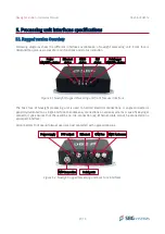
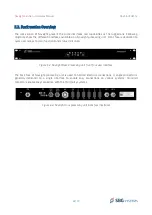
Page 32: ...edicated to quick user access to main functions and status indication The back face of Navsight processing unit is used to hold all electrical connections A single connector is generally dedicated to...

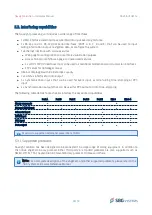
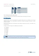
Page 33: ...bus interface for data output 5 x Synchronization inputs that can be used for event input external aiding time stamping or PPS input 2 x Synchronization outputs that can be used for PPS output or data...

Page 34: ...ING ORANGE DGNSS with RTCM data older than 10 seconds ORANGE Stable DGNSS mode with optimal RTCM age BLINKING GREEN Float RTK or PPP solution GREEN Fixed RTK or PPP solution centimetric accuracy INS s...

Page 35: ...ess and hold the button for more than 5 s Reset device settings In case you cannot communicate with the unit anymore unknown Ethernet settings for instance it is possible to restore default settings b...

Page 36: ...ess the web page using the Navsight serial number Indeed the Navsight broadcast a web service so you can connect to the configuration web page using the following address http navsight_020000001 local...

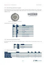
Page 37: ...upports transfer rate at up to 1 Mbits s At the time of writing this document this CAN interface is only used to output log messages By default the CAN interface is disabled The CAN bus implementation...

Page 38: ...AN High 4 GND Signal Ground 5 CAN L CAN Low 6 NC Not internally connected 7 NC Not internally connected 8 NC Not internally connected 5 7 2 Connector specifications rack On the Rack version the CAN bu...

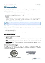
Page 39: ...400 bps 5 8 1 PORT A Interface Although the PORT A shares most of the other serial ports characteristics it has also some specific features Fixed RS 232 communications Dedicated interface for configur...

Page 40: ...n the PORT A is accessible through a standard male DB 9 plug For easier external event interfacing the SYNC IN A is not accessible through the DB 9 plug but a dedicated BNC connector is used instead P...

Page 41: ...r mates with plug ref S31F1C P08MFG0 5500 Connector s pin out is the following Pin Name Description SHIELD SHIELD Connected to the mechanical ground 1 NC Not internally connected 2 SGND Signal ground...

Page 42: ...12 12 V Low level threshold 0 6 1 2 V 1 5 2 0 V Input resistance 3 5 7 k RS 422 Receivers Input differential threshold 200 125 50 mV Input hysteresis 25 mV Input resistance 100 120 155 k RS 232 Trans...

Page 43: ...onnector ref G81F1C P08LFG00000 Other manufacturers such as Fischer provide compatible plugs Fischer Core Series The connector mates with plug ref S31F1C P08MFG0 5500 Connector s pin out is the follow...

Page 44: ...S 422 Tx RS 232 Tx 5 SGND PORT E Signal ground 6 RX RS 422 Rx 7 TX RS 422 Tx 5 8 3 3 Electrical specifications Parameter Conditions Min Typ Max Units RS 232 Receiver Sync In E Input range 12 12 V Low...

Page 45: ...es a pulse each X meters of travel depending on user configuration 5 9 1 1 Electrical specifications Parameter Conditions Min Typ Max Units PPS output Low level output voltage 0 0 1 0 55 V High level...

Page 46: ...t performance the antenna s should be connected before the power is applied The Navsight GNSS receiver estimates the noise floor of the antenna during the startup sequence Note 2 Navsight E versions d...

Page 47: ...es with the following plug reference S31F1C P02LPN0 350S It is also compatible with other manufacturers such as Fischer Core Series Both Rugged processing unit and rack processing unit use the same po...

Page 48: ...er voltage lock out 11 5 V Turn on threshold 8 5 V Turn off threshold Galvanic Isolation 250 VDC VIN to Mechanical Ground VIN to Mechanical Ground 5 14 Typical wiring recommendations In this section w...

Page 49: ...ple resistors on each bus ends as long as the equivalent parallel impedance is 60 This resistor is not present in the rugged processing unit 49 73 Figure 5 20 Main serial interface full duplex connect...

Page 50: ...using a full duplex RS 422 operation The recommended cable is a shielded twisted pairs 26 AWG cable and a termination resistor should be placed at receiver side 50 73 Figure 5 22 Typical wiring diagra...

Page 51: ...it s convenient to the user e g close to LIDAR sensor Two antennas are connected directly on the Navsight processing unit Serial RTK corrections are sent to Navsight unit through PORT D If applicable...

Page 52: ...ient for the user Two antennas are rigidly installed on top of the vessel Serial RTK corrections are received on the PORT D Ethernet interface is used to send back motion information to the MBES top s...

Page 53: ...und such as Molykote 44 medium Failing to do so can lead to the fusion of connector plug and receptacle 6 2 Absolute maximum ratings Stresses above those listed under the Absolute Maximum Ratings may...

Page 54: ...the defective product to the repair center notified by SBG Systems the cost of such shipment being borne by Customer This warranty shall not be construed as covering defects malfunctions or damages c...

Page 55: ...r more information Navsight Variant EKINOX I B Marine IMU EKINOX I S Marine Subsea IMU EKINOX I B Land Air IMU 7 2 Apogee IMU Ordering codes The following Apogee IMU variants are available to order Pl...

Page 56: ...Rugged Land Air INS NAVSIGHT E Rugged Marine MRU NAVSIGHT E Rugged Marine INS NAVSIGHT E Rack Land Air INS NAVSIGHT E Rack Marine MRU NAVSIGHT E Rack Marine INS NAVSIGHT T Rugged Land Air INS GNSS NAV...

Page 57: ...mation about Qinertia SBG Systems 7 6 2 Inertial SDK Software Development Kit The Inertial Software Development Kit is very helpful to configure playback recorded logs export data to text files or thi...

Page 58: ...or subsea It is IP 68 rated but is not suitable for long exposure to salt water It can be delivered in 10 or 20 meters lengths CA NAVS IMU EXT 10M CA NAVS IMU EXT 20M 7 7 2 CA PWR 24 60 CC 4M This ca...

Page 59: ...cable Weight 170g Cable wiring is Pin Signal Color SHIELD NC SHIELD 1 VIN Red 2 VIN Black 7 7 4 CA NAVS ETH 5M This cable provides a direct access to Ethernet network thanks to its RJ 45 plug Direct c...

Page 60: ...general purpose communication cable that can be connected on each serial port available in the rugged processing unit as well as on the CAN bus connector General characteristics are the following 1 x...

Page 61: ...1F1C P08MFG0 5500 plug 1x Male DB 9 plug 1x BNC plug for PPS input SYNC IN IP 68 rating 50cm long Cable wiring depends on the port on which user will connect the cable and is as follows Pin on DB 9 pl...

Page 62: ...Navsight Solution Hardware Manual NAVSIGHTHM 1 5 8 Appendix B Sub systems mechanical outlines All dimensions are in mm 8 1 Ekinox IMU Surface enclosure 8 1 1 Top View 8 1 2 Right view 62 73...

Page 63: ...Navsight Solution Hardware Manual NAVSIGHTHM 1 5 8 1 3 Front view 8 1 4 Bottom view 63 73 28 80 17 70 91 0 10 64 0 10 6 38 0 01 4 H7 2 5 2 5 75 4 H7 4 HOLES 4 50...

Page 64: ...Navsight Solution Hardware Manual NAVSIGHTHM 1 5 8 2 Ekinox IMU Subsea enclosure 8 2 1 Top and bottom views 8 2 2 Front view 64 73...

Page 65: ...Navsight Solution Hardware Manual NAVSIGHTHM 1 5 8 3 Apogee IMU Surface enclosure 8 3 1 Top view 8 3 2 Right view 65 73...

Page 66: ...Navsight Solution Hardware Manual NAVSIGHTHM 1 5 8 3 3 Front view 8 3 4 Bottom view 66 73...

Page 67: ...Navsight Solution Hardware Manual NAVSIGHTHM 1 5 8 4 Apogee IMU Subsea enclosure 8 4 1 Top and bottom views 8 4 2 Front view 67 73...

Page 68: ...Navsight Solution Hardware Manual NAVSIGHTHM 1 5 8 5 Horizon IMU 8 5 1 Top view 8 5 2 Right view 68 73 168 135 215 5 22 55 114 4 3 3 78 72...

Page 69: ...Navsight Solution Hardware Manual NAVSIGHTHM 1 5 8 5 3 Front view 8 5 4 Bottom view 69 73 53 150 187 0 1 153 0 1 203 6 4 H8 2 5 4 H8 2 5 3 3 72 1...

Page 70: ...Navsight Solution Hardware Manual NAVSIGHTHM 1 5 8 6 Processing unit Rugged enclosure 8 6 1 Top view 8 6 2 Right view 70 73...

Page 71: ...Navsight Solution Hardware Manual NAVSIGHTHM 1 5 8 6 3 Front view 8 6 4 Back view 71 73...

Page 72: ...HTHM 1 5 8 7 Processing unit Rack enclosure 8 7 1 Top view 8 7 2 Front view 8 7 3 Back view 72 73 421 7 16 6 in 203 2 8 0 in 224 2 482 6 19 0 in 43 7 1U 19 7 0 19 2 43 2 96 4 124 2 146 2 173 7 200 2 2...

Page 73: ...identify the exact hardware model Finally the Part Number is used for logistics purpose It identifies uniquely the full product configuration including hardware type software options and any software...

Reviews: