Hardware manual PCD1.M2220-C15 │ Document 27-640 – Version ENG03 │ 2020-03-25
Saia-Burgess Controls AG
Communication interfaces
5
5-6
Interfaces using PCD2 plug-in modules PCD2.F2xx
5.3
Interfaces using PCD2 plug-in modules PCD2.F2xx
Please note:
The E-Line CPU has no “Slot A” slot for a PCD7.F1xxS interface module!
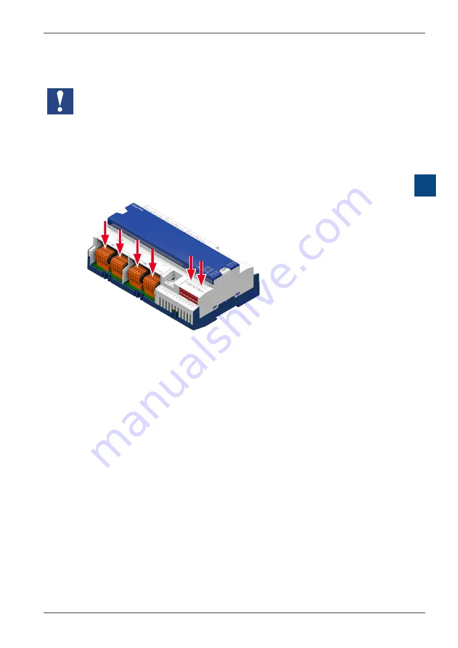
The PCD1.M2220-C15 can be expanded with a maximum of two PCD2.F2xxx
module cards with two fixed interfaces each (carrier card with fixed interface of
choice and a socket for PCD7.F1xxS interface modules) on the two free PCD2
module slots (Slot 0 and Slot 1) that can be equipped.
Maximum 6 serial interfaces
(2x on-board and 2x PCD2.F2xxx (each with 2 interfaces))
PCD1.M2220-C15 with 2 PCD2.F2xx and possibly a PCD7.F1xxxS
5.3.1
General notes for the plug-in module PCD2.F2xxx
System properties of PCD2.F2xxx modules:
The following points must be noted when using the PCD2.F2xxx interface modules:
●
A PCD2.F2xxx module (for 2 interfaces) can be used for each PCD1 system
per I/O slot. This means a total of 4 additional interfaces.
●
The PCD1.M2220-C15 system has a powerful processor that handles both
the application and the serial interfaces. Processing of the interface modules
requires the appropriate CPU capacity. To determine the maximum communica-
tion capacity for each PCD1.M2220-C15, note the following:
The communication volume is determined by the connected peripheral devices.
For example, this applies if a PCD1.M2220-C15 is used as the S-Bus slave sta-
tion. If the PCD1.M2220-C15 is bombarded with heavy telegram traffic at high
baud rates, there is less CPU capacity to handle the actual application. The
following rules apply here:


