25
RT-FS/RT-PHFS OWNER’S MANUAL
10
8
9
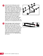
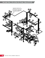
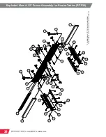
Insert a T-bolt (4.8) through one of the
six holes in the vertical portion of the
router table fence (4.1), so the head of
the T-bolt is on the front of the fence
(the side with three T-slots) and the
threaded portion of the T-bolt is on
the rear of the fence (the side with two
T-slots and the bent edge). Slide an M6
washer (4.7) onto the end of the T-bolt
and then thread a fence face plate lock
knob (4.6) onto the T-bolt, until the end
of the T-bolt is flush with the outer edge
of the lock knob. Repeat this process for
the remaining five holes in the vertical
portion of the router table fence.
Next, you will assemble and install the
32” fence. Thread a ¼” pan head Phillips
screw (4.11) into one of the two holes on
the side of the 2 ½” dust port (4.10), then
thread a ¼” square nut (4.12) partway
onto the end of the screw. Repeat this
process with another ¼” pan head
Phillips screw and ¼” square nut, but
thread the screw in the hole on the other
side of the dust port.
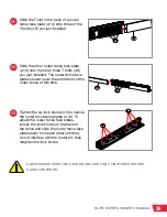
Slide the two ¼” - 20 square nuts (4.12)
into the lower T-slot on the back of the
router table fence (4.1) until the dust
port is aligned with the large opening
in the back of the fence. Use a Phillips
screwdriver to tighten the screws to
secure the dust port to the router
table fence.
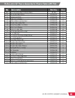
4.11
4.10
4.12
4.12
4.1
4.1
4.8
4.7
4.6

