SawStop ICS31230 Owner'S Manual Download Page 33

SawStop

®

 10” Industrial Cabinet Saw    31

Using Y

our 

Saw

System Initializing 

— this code indicates that the system is performing self-checks and energizing the brake 

system to activate in the case of an accident. This condition should clear within 15 seconds after the Main 

Power Switch is turned on. 
If the ambient temperature is very low (below about 0º F), this code may take longer to clear. The safety system 

detects such low temperatures within the brake cartridge. If necessary, the system turns on a heater inside the 

cartridge to raise the temperature of the electronics. This code will continue until the temperature inside the 

brake cartridge is within the normal operating range.

System Ready 

— this code indicates that all self-checks have been completed, the safety system is operating 

properly, and the saw is in Standby mode ready to run.

Replace the Brake Cartridge 

— this code indicates that the cartridge has already been fired or there is some 

other permanent defect that cannot be corrected. If the cartridge has not been fired, turn off the Main Power 

and turn it back on. If the error continues, install a new cartridge.

Blade is Coasting Down 

— this code indicates that the blade is coasting down and that the safety system 

is ready to activate the brake if contact is detected. The safety system detects the rotation of the motor to 

determine when the blade is coasting down. If you touch the blade while this code is flashing, the brake will 

activate. 

ALWAYS MAKE SURE THE BLADE HAS COME TO A COMPLETE STOP AND THE COAST 

DOWN STATUS CODE HAS CLEARED BEFORE TOUCHING THE BLADE!

Bypass Mode is 

ON


— this code indicates that the saw is running in Bypass Mode and 

will not

 activate the 

brake in the event of accidental contact with the blade. Bypass Mode allows you to cut electrically conductive 

materials such as aluminum without activating the brake. When the saw is in Bypass Mode, the safety system 

disables the brake. See page 33 for instructions on how to use the saw in Bypass Mode.

Push the Start/Stop Paddle to 

OFF


— this code indicates that the Start/Stop paddle was left in the 

ON 

position (i.e., pulled out). Push the paddle in to the 

OFF

 position to clear this error. This is a safety feature to 

prevent the saw from restarting after a power loss or after the safety system has turned the saw off due to an 

error detected during use.

Turn the Cartridge Key to 

ON


— this code indicates that the cartridge locking key is not turned to 

ON

. To 

clear this error make sure the cartridge locking key is correctly installed and turned to 

ON

. See page 45 for 

instructions on how to install and turn on the cartridge key.

No Blade Rotation 

— this code indicates that the motor is not able to spin the blade as expected when the 

Start/Stop Paddle was pulled out. The most common cause of this error is an open access door. Check to 

make sure both the Belt Access Door and the Motor Cover are fully closed and that the corresponding interlock 

switches are actuated. See page 26 for instructions on adjusting the position of the interlock switches.

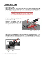
Adjust Position of the Brake Cartridge 

— this code indicates that the blade is too far from the aluminum 

brake pawl. To clear this error, adjust the position of the brake cartridge as described on page 18. This error 

code will also be displayed if there is no blade installed, if a blade smaller than 10 inch is installed, or if a non-

conductive blade (e.g. abrasive blade) is installed. 

Using Your Saw

Summary of Contents for ICS31230

Page 1: ...10 INDUSTRIAL CABINET SAW Models ICS31230 ICS31240 50 ICS51230 ICS53230 ICS53415 50 ICS53480 ICS53600 ICS73230 ICS73480 ICS73600 OWNER S MANUAL SawStop...

Page 2: ...12 7228772 7284467 7308843 7350445 7472634 7481140 7525055 7536238 7600455 7610836 7640835 7661343 7681479 7707918 7707920 7788999 7789002 7827890 7827893 7832314 7836804 7866239 7895927 7921754 79588...

Page 3: ...ntact the moving blade the technology will detect that contact and stop the blade in milliseconds to minimize any injury This manual tells you more about your saw and how to operate and maintain it Pl...

Page 4: ...on Wing Cleaning 16 4 Rip Fence Installation 16 5 Tilt Hand Wheel Handle Installation 17 6 Blade or Dado Installation 17 7 Brake Position Adjustment 18 8 Blade Guard Riving Knife Installation 20 9 Tab...

Page 5: ...ation Assembly 51 3 Aligning the Blade to the Tilt Axis 53 4 Adjusting the Elevation Limit Stops 57 5 Adjusting the Tilt Limit Stops and Tilt Angle Indicator 59 6 Adjusting the Table Insert 61 7 Adjus...

Page 6: ...5 HP 82 415V Three Phase 5 HP 83 480V Three Phase 5 and 7 5 HP 84 600V Three Phase 5 and 7 5 HP 85 Cabinet and Table Assembly Exploded View 86 Cabinet and Table Assembly Parts List 87 Internal Assembl...

Page 7: ...mplied warranties including merchantability and fitness for a particular purpose SawStop shall not be liable for death injuries to persons or property or incidental consequential contingent or special...

Page 8: ...ding dust masks or respirators designed to filter out such dust and chemicals 3 THIS SAW MUST BE CONNECTED TOAGROUNDED WIRING SYSTEM or to a system having an equipment grounding conductor In the event...

Page 9: ...ple check the alignment of moving parts look to see whether moving parts are binding or rubbing check to see whether parts are broken make sure accessories are properly mounted in the saw and check an...

Page 10: ...d and spreader for every operation for which it can be used including all through sawing 3 Keep hands out of the line of the saw blade 4 Use a push stick when required 5 Know how to reduce the risk of...

Page 11: ...equate ground may cause the safety system to malfunction and could result in a serious injury WARNING Connect Only 460 480 Volts Three Phase Power This machine must be connected to an electrical groun...

Page 12: ...pression If the electronic detection unit detects contact while the blade is spinning including during coast down the fuse is burned by a surge of electric current The spring then pushes an aluminum b...

Page 13: ...started without a blade installed Since the safety system disables the motor if the blade is spaced too far from the brake a missing blade will be detected as a blade to brake spacing error and the m...

Page 14: ...pressure treated wood is wet the combination of copper and water substantially increases the conductivity of the wood Therefore allow wet pressure treated wood to fully dry before cutting Typically t...

Page 15: ...with motor 2 Two extension wings the right extension wing is pre installed 3 One blade guard and spreader with anti kickback pawls 4 One riving knife pre installed 5 One 10 inch saw blade 6 One zero...

Page 16: ...ension Wings 3 Blade Guard 4 Standard Table Insert 5 Switch Box 6 Elevation Hand Wheel 7 Tilt Hand Wheel 8 Motor Cover 9 Terminal Box 10 Dust Port 11 Miter Gauge 12 Blade Wrenches 2 13 Belt Access Doo...

Page 17: ...9 Arbor Belt 30 Motor Belt 31 Dust Shroud Door 32 Upper Elevation Limit Bolt 33 Lower Elevation Limit Bolt 34 0 Tilt Limit Bolt 35 45 Tilt Limit Bolt 36 Brake Positioning Bolt 37 Brake Cartridge 38 Ca...

Page 18: ...me the table and wing surfaces can also be protected by applying a light coating of oil and then covering with wax paper 4 Rip Fence Installation This saw ships without a rip fence You must install a...

Page 19: ...s designed for use with standard 10 inch blades with kerfs from 3 32 inch to 3 16 inch Blades with kerfs much thinner than 3 32 inch should not be used because those blades might not be strong enough...

Page 20: ...e table top The bolt will be accessible through the opening in the table top To install the blade use the open end of one of the blade wrenches included with the saw to hold the arbor behind the arbor...

Page 21: ...the point on the brake pawl that is closest to the blade may be at the end of the brake pawl rather than the middle if the diameter of the blade is slightly less than 10 inches The exact distance is...

Page 22: ...important tool for reducing the potential for kickback when the blade guard cannot be used The riving knife should always be used whenever you need to make rabbet or other non through cuts where the b...

Page 23: ...for which it can be used including all through sawing Setting Up Your Saw Lower the clamping handle completely to lock the spreader in place see Fig 16 After you have installed the table insert as de...

Page 24: ...t the heads of the rear lock down screws in the bottom of the insert slide under the heads of the lock down screws in the table opening see Figs 17 and 18 Then lower the front end of the insert into t...

Page 25: ...s physical hazard Your SawStop saw is designed to provide superior dust collection both above and below the table A dust shroud below the table is engineered to capture the airflow generated by the sp...

Page 26: ...voltage amperage and phase required Attempting to operate the saw on a power supply different than specified on the specification label will void all warranties and may result in serious injury as we...

Page 27: ...djustments maintenance or repairs to the saw including changing blades installing or removing the blade guard and riving knife etc Setting Up Your Saw In addition the disconnect switch can be locked i...

Page 28: ...wer front edge of the access door opening as shown in Fig 25 The switch has a lever type actuator and is mounted on a bracket that is attached to the inside of the cabinet by two screws If necessary y...

Page 29: ...7 for instructions CAUTION When adjusting the height or tilt angle of the blade reverse the hand wheel slightly to release tension after reaching the limit stops This prevents any slight twisting of t...

Page 30: ...he electrical power is interrupted Using Your Saw After ensuring that the Start Stop paddle is in the OFF position i e pushed in turn the Main Power Switch to the ON position by flipping the toggle up...

Page 31: ...you have finished using the saw turn the Main Power Switch to OFF to reduce the likelihood of inadvertent start up In addition the Main Power Switch has a lockout key that you can remove to prevent c...

Page 32: ...n routine is completed you should not see the red light unless there is a problem If this happens find the System Status code below see Fig 31 to determine how to correct the problem WARNING Always tu...

Page 33: ...tes that the saw is running in Bypass Mode and will not activate the brake in the event of accidental contact with the blade Bypass Mode allows you to cut electrically conductive materials such as alu...

Page 34: ...onductive and you can make future cuts in normal mode See page 33 for instructions on how to operate the saw in Bypass Mode Overload Due to Wet Wood this code indicates that the wood being cut is too...

Page 35: ...LED will begin blinking slowly and the red LED will flash once to let you know when the 1 second has elapsed Note to prevent unauthorized use of the saw in Bypass Mode remove the Bypass Key from the s...

Page 36: ...supports all the other components of the assembly helps minimize kickback by preventing a workpiece from pinching or shifting into the back of the blade Large and small anti kickback pawls on each si...

Page 37: ...n be pivoted upward to a balance point where it will stay without further support This allows you to adjust or change the blade without removing the guard Install the blade guard as described on page...

Page 38: ...her the guard nor the riving knife can be used is making dado cuts To use the riving knife remove the blade guard and install the riving knife as described on page 20 When the blade guard riving knife...

Page 39: ...til it stops Next rotate the miter gauge head counter clockwise until the index stop hits the indexing pin and then tighten the handle to lock the gauge at the desired angle The index stops are preset...

Page 40: ...the miter gauge to the desired miter angle see page 37 Position the workpiece against the miter gauge head and slowly push the miter gauge toward the non spinning blade until the workpiece is almost...

Page 41: ...esult Position the workpiece flat on the table and flush against the side of the rip fence Turn on the motor Use both hands to push the workpiece smoothly toward the blade as shown in Figs 42 and 43 I...

Page 42: ...non through cuts the blade guard and spreader must be removed For these cuts install the riving knife except when making dado cuts and use one or more featherboards to hold down the workpiece and help...

Page 43: ...sealed to inhibit the entry of dust and other debris you should periodically check the cartridge visually for the presence of dust inside the housing as this might indicate that the seal has been dama...

Page 44: ...The brake cartridge is mounted beneath the table and behind the blade see Fig 47 To change the cartridge begin by setting the tilt angle to about 0 and raising the blade elevation to close to the maxi...

Page 45: ...positioning pin extend outward from a cartridge mounting bracket that sets the position of the cartridge The cartridge mounting bracket also holds a computer cable that self aligns to the computer co...

Page 46: ...arbor block a short distance see Fig 52 Only move the blade and cartridge a short distance each step for example a distance equal to one or two threads on the arbor Otherwise the blade and cartridge m...

Page 47: ...is not actuated If you attempt to turn on the saw when the key is not in the locked position the LED lights on the Switch Box will flash a status code as described on page 30 Turning the key to the lo...

Page 48: ...be reused after the brake is activated and it may be discarded Once the activated cartridge has been removed obtain another brake cartridge that has not been activated and follow the instructions on p...

Page 49: ...described first and provides an accuracy of about 0 002 inch An alternative procedure is also described which provides an accuracy of about 0 010 inch Preferred Table Alignment Procedure To align the...

Page 50: ...e direction this indicates that the left and right surfaces of the blade are not parallel Rotate the blade 1 4 turn and repeat the process from the beginning If you cannot get consistent readings try...

Page 51: ...Adjust the screws until the readout is the same but in the reverse direction For example if the initial reading was 0 006 inch adjust the positioning screw until the reading is 0 006 inch Now slide t...

Page 52: ...miter slot and the left side of the blade Make sure to measure to the flat plate of the blade rather than the tooth If you are using a combination square set the end of the ruler flat against the rig...

Page 53: ...nt and rear trunnions This blade elevation assembly is aligned by adjusting the angle of the rear shaft so that it is parallel with the front shaft When the front and rear shafts are parallel the blad...

Page 54: ...imately inch inside the front edge of the blade and about inch higher than the top of the arbor washer see Fig 54 Measure the parallelism of the blade relative to the miter slots in the table as descr...

Page 55: ...il the difference between the first and second measurements is within 0 002 inch 3 Aligning the Blade to the Tilt Axis When making bevel cuts the blade is tilted on an axis that runs along the surface...

Page 56: ...t hand wheel against the 45 limit stop Now reposition the dial indicator measurement arm against the right side of the blade and about 1 4 inch directly above the arbor flange Slide the dial indicator...

Page 57: ...onnected to the rear trunnion by two bolts that extend through oversized holes in the v bracket The oversized holes allow the position of the v bracket to be adjusted relative to the rear trunnion Usi...

Page 58: ...ts that attach the v bracket to the rear trunnion The blade should now be parallel to the tilt axis Since the alignment of the blade has been changed the table must now be realigned Align the table as...

Page 59: ...of the elevation plate see Fig 68 You can access the upper limit bolt by opening the motor cover The head of the bolt is painted yellow for easy identification To adjust the position of the upper limi...

Page 60: ...inch at the lowest elevation This should also ensure that a 10 inch blade is at least 1 8 inch below the top of the table Lower the blade elevation until the lower limit stop is engaged If the bumper...

Page 61: ...able see Fig 70 The 0 tilt limit stop is set by the bolt mounted in the upper left portion of the front trunnion bracket see Fig 71 You can access the bolt by opening the belt access door on the left...

Page 62: ...e by tightening the locking screw Making Adjustments to Your Saw 45 Tilt Limit Stop To check the position of the 45 limit stop install a 10 inch saw blade on the arbor see page 17 Raise the blade to i...

Page 63: ...table top The insert is pre cut at the factory with a 10 inch blade after all alignments to the saw have been completed As shown in Fig 75 the insert includes front and rear leveling screws to set the...

Page 64: ...rear of the table insert is held down by a pair of lock down screws mounted in the table at the rear of the table opening As shown in Fig 77 the lock down screw heads overlap the heads of the rear lev...

Page 65: ...ft side of the spreader is flush and flat against the straight edge If necessary pivot the left anti kickback pawl up out of the way while performing this step Note if you are using a thin kerf blade...

Page 66: ...g knife is not correct use the elevation handwheel to set the top of the blade to be between 1 5 mm above the top of the table Next remove the table insert and loosen the two vertical positioning bolt...

Page 67: ...ese two bolts rotate the back of dust port until the wood stop is 7 10 mm above the table Adjusting the Height of the Limit Rod When set correctly the wood stop at the end of the limit rod will preven...

Page 68: ...spring designed to push the clamp open when the handle is raised Therefore you will have to push the handle toward the clamp against the force of the spring When the handle is fully pressed against t...

Page 69: ...pair of socket head mounting bolts A hex head support bolt extends from the bottom of the front trunnion bracket to push against the bottom of the tilt shaft bracket The support bolt prevents the til...

Page 70: ...To begin loosen the miter gauge head by turning the locking handle counter clockwise about 1 2 turn see Fig 87 Next for the indexing stop you want to adjust loosen the corresponding locking nut and t...

Page 71: ...out 0 001 Maximum Allowable Runout Blade Lateral Movement Over Full Elevation Range 0 006 Maximum Table Flatness Measured Diagonally 0 010 Maximum Gap Overall Table and Extension Wing Flatness 0 025 M...

Page 72: ...tom of the trunnion assembly and the dust port on the back of the cabinet can be detached from the trunnion assembly and used to vacuum out the cabinet using the dust collection system connected to th...

Page 73: ...rake did not activate 1 The Start Stop paddle was bumped 1 Ensure the Start Stop paddle is in the OFF position and restart the saw 2 The material being cut is overloading the safety detection system e...

Page 74: ...aligned with the pivot and positioning pins 2 There is debris on the pivot or positioning pins or in the cartridge mounting holes 2 Make sure the pins and mounting holes are clean and free of obstruct...

Page 75: ...e only a 10 inch diameter blade with a standard brake cartridge or an 8 inch dado set with a dado cartridge The gears sound feel rough when raising or lowering the blade 1 There is dust or debris on t...

Page 76: ...h pitch gum or other material 2 Clean or replace the blade 3 The blade is not the correct blade for the material or cut 3 Replace the blade The saw vibrates too much 1 The blade is damaged or unbalanc...

Page 77: ...SawStop 10 Industrial Cabinet Saw 75 Cabinet Saw Dimensions Front View Rear View 34 19 1 4 4 3 8 44 24 5 2 1 8 12 21 7 8 5 7 8 12 1 2 11 1 8 8 7 8 9 3 4 5 5 2 1 8 2 1 8 3 8 7 8...

Page 78: ...76 SawStop 10 Industrial Cabinet Saw Cabinet Saw Dimensions Left Side View Footprint 3 12 24 30 1 33 7 8 24 3 4 27 3 8 31 3 4 1 3 4 24 3 4 19 1 4...

Page 79: ...ypical pushstick Pushsticks should be constructed from material that is sturdy and electrically non conductive such as scrap wood Pushsticks should always be used when your hand comes within 6 inches...

Page 80: ...pical push block It includes the three pieces shown here labeled A B and C Cut piece A out of 3 4 inch plywood and cut pieces B and C out of 1 2 thick plywood Attach piece A to the center of piece B u...

Page 81: ...ary fence place it on the saw with piece B flat on the table top and piece A against the left side of the rip fence Position the auxiliary fence so that the front edge of piece B is 1 2 inches back fr...

Page 82: ...should be constructed from good quality wood that is free of knots Use Featherboards to help keep the material being cut in contact with the table and to help prevent kickback Do not use featherboard...

Page 83: ...to your saw Green G r e e n Green Green White White White B l a c k Black Green White Black Black Black White Black White White Black White BELT ACCESS DOOR INTERLOCK SWITCH MOTOR COVER INTERLOCK SWI...

Page 84: ...TO MOTOR TO SWITCH BOX MAGNETIC CONTACTOR BOX DISCONNECT SWITCH TERMINAL BOX Green G r e e n Green Green White White White B l a c k Black Green White Black Black Black White Black White White Black W...

Page 85: ...OIL TO MOTOR TO SWITCH BOX MAGNETIC CONTACTOR BOX Green Green Red White Black White Black Black White 97 98 Red GROUND PLATE Black FUSE Black Red Red Black White Black Black Red White 415V TRANSFORMER...

Page 86: ...4T2 6T3 2T1 4T2 6T3 95 96 A2 COIL A1 COIL TO MOTOR TO SWITCH BOX MAGNETIC CONTACTOR BOX Green Green Red White Black White Black Black White 97 98 Red GROUND PLATE Black FUSE Black Red Red Black White...

Page 87: ...COIL TO MOTOR TO SWITCH BOX MAGNETIC CONTACTOR BOX Green Green Red White Black White Black Black White 97 98 Red GROUND PLATE Black FUSE Black Red Red Black White Black Black Red White 600V TRANSFORM...

Page 88: ...Amps 1 Phase 3 HP 3450 RPM c US 175370 S a w S t o p To avoid loss of SawS top prote ction durin g coas t down do not turn off Main Pow er until blad e has stop ped spin ning WA RNI NG WARNING Moving...

Page 89: ...re CB104 021 1 21 Cover Plate for Tilt Rod Aperture CB104 022 1 22 M6x1 0x16 Phillips Head Screw CB104 023 2 23 Blade Wrench CB104 024 2 24 Blade Wrench Bracket CB104 025 1 25 M8x1 25x10 Socket Head B...

Page 90: ...n Label 5HP 3PH 230Volt CB107 038 Specification Label 5HP 3PH 480Volt CB107 039 Specification Label 7 5HP 3PH 230Volt CB107 040 Specification Label 7 5HP 3PH 480Volt CB107 041 Specification Label 5HP...

Page 91: ...70 Contactor Box Mounting Plate CB104 284 1 71 M6x1 0x10 Pan Head Phillips Screw CB104 285 4 72 Motor Cover Interlock Switch CB105 017 1 73 M4x0 7x35 Pan Head Phillips Screw CB105 030 2 74 M4x12x1 Was...

Page 92: ...53 52 31 30 107 39 31 66 11 48 44 43 38 56 96 16 18 24 27 28 29 9 77 74 45 42 78 15 71 73 19 12 46 47 26 15 33 62 61 64 63 106 73 84 74 81 75 7 72 60 15 19 75 72 68 67 74 16 14 15 69 70 34 105 79 41...

Page 93: ...1 4 Motor Pulley CB104 076 1 Motor Pulley 50 Hz motors only CB106 033 5 M5x5x30 Key CB104 077 1 6 M6x1 0x8 Set Screw CB104 078 2 7 Tilt Lock Knob CB104 079 1 8 Front Trunnion Bracket CB104 080 1 9 Ta...

Page 94: ...it Bolt CB104 120 1 49 Rear Elevation Shaft CB104 121 1 50 M16 External Retaining Ring CB104 122 1 51 M16x25x1 5 Washer CB104 123 1 52 Eccentric Bushing CB104 124 1 53 M12 External Retaining Ring CB10...

Page 95: ...ing Plate Cam Bushing CB104 165 1 94 Clamp Handle CB104 166 1 95 M4x0 7x6 Set Screw CB104 167 1 96 Spring CB104 168 1 97 M8x1 0x40 Hardened Hex Head Bolt CB104 169 1 98 M13x28x3 Washer CB104 170 2 99...

Page 96: ...strial Cabinet Saw Arbor Assembly Exploded View 3 2 4 5 13 24 18 17 10 16 8 10 9 17 10 12 11 15 14 32 33 34 42 31 29 36 37 28 48 49 50 44 39 53 51 30 52 35 41 38 40 46 47 45 26 43 21 25 6 7 54 1 22 20...

Page 97: ...04 189 1 19 M5x0 8x10 Pan Head Philips Screw CB104 190 1 20 M5 External Tooth Lock Washer CB104 193 1 21 Arbor Belt CB104 191 1 22 Motor Belt CB104 192 1 Motor Belt 50 Hz motors only CB112 001 23 8 32...

Page 98: ...Retraction Spring Sleeve CB104 218 1 48 M8x1 25x25 Hex Head Bolt CB104 219 1 49 M8x16x1 Washer CB104 220 1 50 Retraction Pawl Sleeve CB104 221 1 51 M10x1 5x25 Socket Head Bolt CB104 222 2 52 M10 Lock...

Page 99: ...SawStop 10 Industrial Cabinet Saw 97 This page is blank...

Page 100: ...6 15 30 45 60 37 38 39 40 41 40 41 42 43 44 45 46 47 47 48 49 50 51 52 53 54 54 55 56 57 58 59 60 60 61 62 62 63 64 65 64 WARNING 1 Use the blade guard and spreader for every operation for which it ca...

Page 101: ...02 1 39 M3x1 06x8 Pan Head Phillips Screw TSG DC 003 7 40 M4x1 6x8 Pan Head Phillips Screw TSG DC 004 2 41 M4x16x3 Polycarbonate Custom Washer TSG DC 005 2 42 Inner Left Guard Shell Extension TSG DC 0...

Page 102: ...llips Screw TSG DC 026 4 63 M4x0 7 Hex Nut TSG DC 027 4 64 Dust Collection Port Compression Spring TSG DC 028 2 65 M4x10 Spring Pin TSG DC 029 1 66 Blade Guard Warning Label TSG DC 030 1 67 Limit Rod...

Page 103: ...t Assembly p n TSI DLD with lock down lever Dust Collecting Blade Guard Assembly p n TSG DC Miter Gauge Assembly p n CB104 250 ICS Push Stick p n CB110 009 Owner s Manual p n CB110 010 Over Arm Dust C...

Page 104: ...lade elevation assembly 51 53 riving knife and spreader 63 65 table 47 50 tilt axis 53 56 Ambient Temperature 31 Anti Kickback Pawl s 21 34 Arbor belt 12 15 69 70 block 15 46 58 diameter 69 nut 15 18...

Page 105: ...ing Bolt 15 18 Bypass key 14 24 33 mode 5 10 11 31 33 C Cabinet Saw dimensions 75 76 specifications 69 Cartridge see Brake Cartridge Cartridge Key 13 15 31 41 45 Clamping Handle for spreader or riving...

Page 106: ...handwheel 14 27 elevation locking knob 27 elevation plate 15 51 52 56 58 elevation threaded rod 15 limit stops 57 58 Exploded Views arbor assembly 94 cabinet and table assembly 86 internal assembly 90...

Page 107: ...57 58 tilt 59 60 Lock Out 25 29 M Main Power Switch 7 10 12 28 33 Maintenance 5 25 70 Material Conductivity Test 32 Miter Gauge adjustment 36 37 68 indexing pin 37 68 index stop s 37 68 slot s 14 36...

Page 108: ...bypass mode 5 10 11 31 33 operation 5 10 12 28 33 46 70 system status codes s 10 30 33 Setting Up Your Saw 16 26 Shipping Weight 69 Single Phase Power 24 81 Specification Label 24 Specifications 69 S...

Page 109: ...eel 13 14 17 27 limit stop 27 59 60 locking knob 27 Troubleshooting 71 74 Trunnion Brace 58 U Unpacking Your Saw 13 Using Your Saw 27 45 V V bracket 55 56 W Warning Labels 8 9 Warranty 5 12 24 Wet Woo...

Page 110: ...SawStop LLC 11555 SW Myslony Street Tualatin Oregon 97062 USA www sawstop com phone 503 570 3200 fax 503 570 3303 email info sawstop com July 2018 M ICS 19 0002 00...

Reviews: