background image

16

EN

CASSETTE - FLOOR-CEILING - DUCTED UNITS

 / Installation Manual

17

9.3  RECOMMENDED INSTALLATION PROCESS

It is recommended carrying out the installation in the follo-
wing order:

• Installation of the condensed water pipe.
• Installation of the refrigerant pipes.
• Installation of the fresh air and bypass lines.
• Electrical installation.
• Indoor unit assembly in the ceiling.
• Connections.
• Checking for leaks and starting the unit.
• Assembly of the decorative panel.

9.4  INSTALLATION OF THE CONDENSED WATER PIPE

9.4.1  HANDLING THE CONDENSED WATER PIPE


  WARNING!

Danger  of  breakdowns  or  malfunction.  Danger  of 
incorrect drainage of the condensed water and wear of 
materials due to dripping water.
Take the following points into consideration:
-   Ensure  that  air  circulates  through  the  condensed 

water pipe in order to guarantee that the water can 
be freely released. Otherwise, the condensed water 
could leak through the indoor unit body.

-   Mount the pipe without bending it in order to avoid 

blockage.

-   If the water pipe is channelled outdoors, ensure that 

it is insulated against freezing.

-   If the condensed water pipe is installed in a room, fit 

thermal insulation.

-   Avoid installing the condensed water pipe with an 

ascending bend.

-   Avoid  installing  the  condensed  water  pipe  with  it 

free end submerged in water.

-   Avoid  installing  the  condensed  water  pipe  with 

crimping.

-   Install the condensed water pipe in such a way that 

the distance of its free end from the floor is at least 
5 cm.

-   Install the condensed water pipe in such a way that 

its free end is kept away from unpleasant odours to 
ensure that they do not penetrate the room.

9.4.2 LAyING OF THE CONDENSED WATER PIPE


  NOTE!

The indoor unit is fitted with a condensed water removal 
pump.


  NOTE!

Use a pipe whose diameter is at least the same as the 
diameter  of  the  indoor  unit  connection  (polyethylene 
pipe: inner diameter 25 mm, outer diameter 32 mm).

• Plan  the  layout  of  the  condensed  water  pipe  taking  into 

account the indications in section 9.4.1.
-  Ensure that the pipe is as short as possible.
-  Ensure that the minimum inclination from the indoor unit 

is at least 1%.

• Mount the pipe supports taking into account the distances 

and inclinations indicated in figure 9.1.
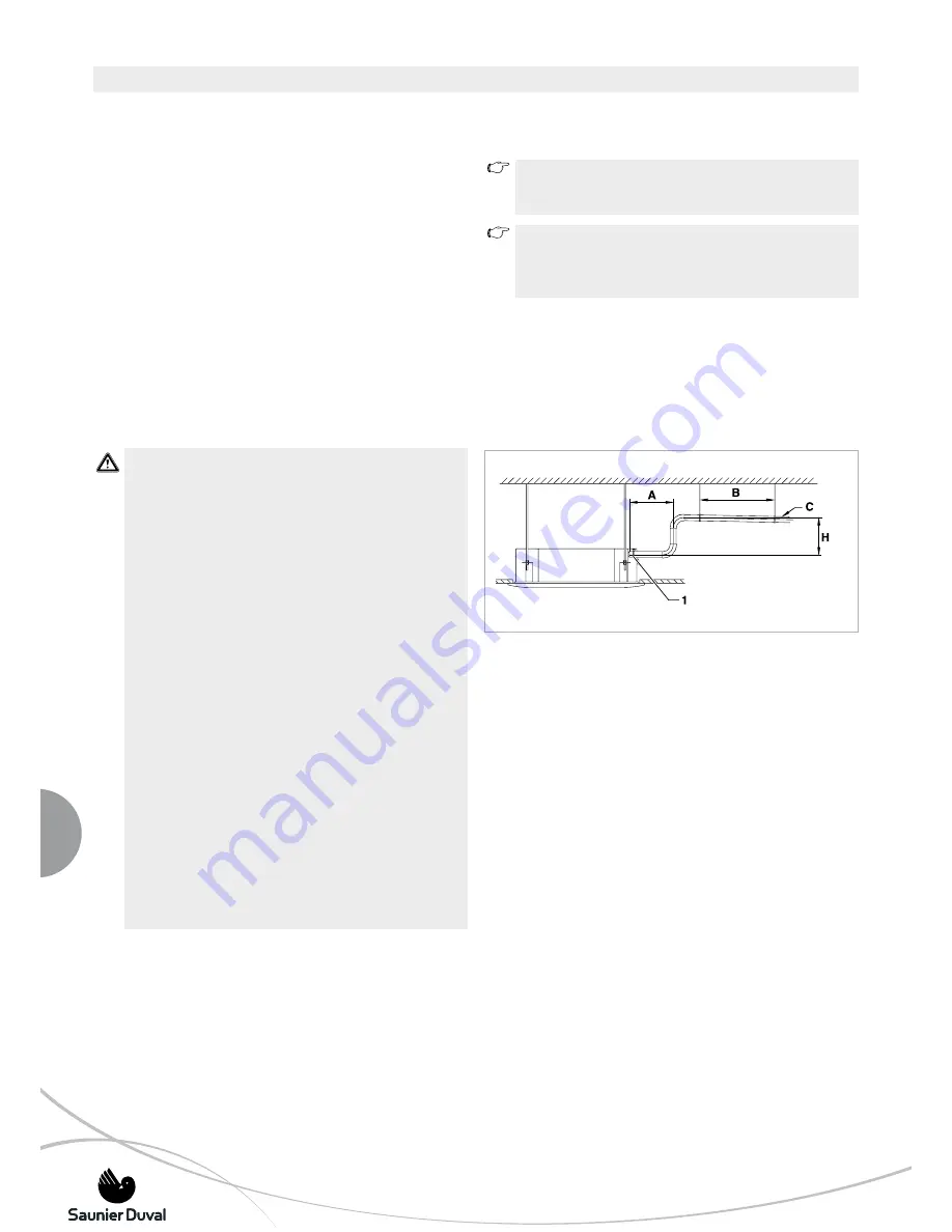
Fig. 9.1 

 Installation diagram of the Pipe for the Drainage of the 
Condensed Water.

Legend

1  Pump flange (jacketing)
A Distance with regard to the indoor unit 
  (maximum 00 mm)
B Distance between supports (maximum 1 - 1.50 m)
C Pipe inclination (minimum 1%)
H Maximum  height  of  the  pipe  with  regard  to  the  pump 

(maximum 500 mm)

• Mount the condensed water pipe in its supports.

-  Prevent  the  pipe  from  bulging  to  guarantee  the  correct 

removal of the water.

• Insulate the pipe with thermal insulation.

9 INSTALLATION OF THE CASSETTE INDOOR UNIT

Summary of Contents for SDH 10-051 NF

Page 1: ...CASSETTE FLOOR CEILING DUCTED UNITS SDH 10 051 NK SDH 10 066 NK SDH 10 090 NK SDH 10 105 NK SDH 10 130T NK SDH 10 051 NF SDH 10 066 NF SDH 11 050 ND SDH 11 065 ND SDH 11 090 ND SDH 11 105 ND Installation Manual ...

Page 2: ... duct 21 10 INSTALLATION OF THE FLOOR CEILING INDOOR UNIT 22 10 1 General Warnings 22 10 2 Mounting of the indoor unit 22 10 2 1Preparing indoor unit installation 22 10 2 2Floor installation 22 10 2 3Ceiling installation 23 10 3 Installation of the Refrigerant pipes 24 10 3 1 Handling the Refrigerant Pipes 24 10 3 2Laying of the Refrigerant Pipes 24 11 INSTALLATION OF THE DUCTED INDOOR UNIT 25 11 ...

Page 3: ...allation manual and user manual NOTE This equipment contains R 410A refrigerant Do not vent R 410A into atmosphere R 410A is a fluorinated greenhouse gas covered by Kyoto Protocol with a Global Warming Potential GWP 1975 NOTE The refrigerant fluid contained in this equipment must be properly recovered for recycling reclamation or destruction before the final disposal of the equipment NOTE The rele...

Page 4: ... declares that this unit has been designed and constructed in compliance with the standard in force with regard to obtaining the CE Marking 5 DESCRIPTION OF THE UNIT This unit is comprised of the following elements Indoor unit Outdoor unit Remote controller Connections and channels Accessories Figure 5 1 shows the unit components Fig 5 1 Unit components Legend 1 Indoor Unit example cassette 2 Outd...

Page 5: ...imensions of the Indoor Units 10 066 NHKI 10 090 NHKI 10 105 NHKI and 10 130 NHKI MODEL H L D h l d I J Kg 10 051 NHKI 254 650 650 30 580 580 610 400 21 10 066 NHKI 230 950 950 46 840 840 775 680 29 10 090 NHKI 300 950 950 46 840 840 775 680 36 10 105 NHKI 300 950 950 46 840 840 775 680 36 10 130 NHKI 300 950 950 46 840 840 775 680 36 Table 5 1 Dimensions mm and Weights Electrical wiring Liquid an...

Page 6: ...nit Fig 5 4 Dimensions of the Indoor Units MODEL H L D Kg 10 051 NHKI 660 990 203 29 10 066 NHKI 660 990 203 29 Table 5 2 Dimensions mm and Weights 5 3 Ducted Indoor unit Fig 5 5 Outline dimensions of the indoor ducted units and air outlet opening size Fig 5 6 Air return opening size Electrical wiring Air filter ...

Page 7: ... hooks Kg L H D C E F G B I J K A M SDH 11 050 NHDI 920 210 635 570 65 713 35 119 815 200 80 960 350 26 SDH 11 065 NHDI 920 270 635 570 65 713 35 179 815 260 20 960 350 30 SDH 11 090 NHDI 1140 270 775 710 65 933 35 179 1035 260 20 1180 490 41 SDH 11 105 NHDI 1140 270 775 710 65 933 35 179 1035 260 20 1180 490 41 SDH 11 130 NHDI 1200 300 865 800 80 968 40 204 1094 288 45 1240 500 49 Table 5 3 Dimen...

Page 8: ...nit 10 050 NHFKDO 10 065 NHFKDO and 10 090 NHFKDO Legend H Height L Length D Depth A Length of valves B Distance between valves C Distance from the highest valve to the floor I Distance between fixing holes J Distance between fixing supports MODEL H L D A B C I J kg 10 050 NHFKDO 695 845 315 60 60 280 335 560 59 10 065 NHFKDO 862 895 305 60 60 280 333 590 73 10 090 NHFKDO 990 990 340 60 60 280 366...

Page 9: ...g connections and channels Gas G and liquid channels L they carry the cooling agent between the outdoor and indoor unit Discharge channels for condensed water in the outdoor and indoor unit they allow the water to be properly dis charged which condenses during the normal operation of the unit Electric connections they supply electric energy to the unit 5 7 Accessories This unit is provided with th...

Page 10: ... pressure level dB A 35 40 42 35 40 42 37 41 44 37 41 44 37 41 44 Outdoor Unit Air Flow volume m3 h 2300 2570 2850 3200 4800 5000 5800 6000 5800 6000 Sound pressure level dB A 45 50 46 51 46 51 48 53 50 55 Refrigerant R410A Refrigerant charge gr 1600 2300 3350 4100 3850 Compressor type Rotary DC Inverter Scroll DC Inverter Expansion system EXV Capillary Pipe Connections Pipe connection liq gas inc...

Page 11: ...2 45 Outdoor Unit Air Flow volume m3 h 2300 2570 2850 3200 Sound pressure level dB A 45 50 46 51 Refrigerant R410A Refrigerant charge gr 1600 2300 Compressor type Rotary DC Inverter Expansion system EXV Capillary Pipe Connections Pipe connection liq gas inches 1 4 1 2 3 8 5 8 Max Piping length m 30 30 Max height IU under OU m 15 15 Max height OU under IU m 10 10 Chargeless length m 5 5 Additional ...

Page 12: ...2 Sound pressure level dB A 31 34 37 32 35 41 34 41 43 34 41 43 35 42 44 Outdoor Unit Air Flow volume m3 h 2300 2570 2850 3200 4800 5000 5800 6000 5800 6000 Sound pressure level dB A 45 50 46 51 46 51 48 53 48 53 Refrigerant R410A Refrigerant charge gr 1600 2300 3350 4100 4450 Compressor type Rotary DC Inverter Expansion system Capillary Pipe Connections Pipe connection liq gas inches 1 4 1 2 3 8 ...

Page 13: ...wing the local environmental standards in force Do not dispose of it without the proper controls 8 INSTALLATION 8 1 Qualification of the installation personnel Ensure that this unit is installed by authorised personnel The personnel authorised by Saunier Duval must be suitably qua lified and able to install the unit correctly 8 2 General precautions to be taken into account before starting the ins...

Page 14: ...ration opposite side connections minimum 20 cm F Rear separation minimum 20 cm G Side separation connections side minimum 30 cm H Front separation minimum 100 cm I Distance between the Ceiling and the False Ceiling see table 8 1 Fig 8 2 Minimum assembly distances cassettes MODEL A B C D I 10 051 NHKI 1000 1000 1000 1000 340 10 066 NHKI 1000 1000 1000 1000 330 10 090 NHKI 1000 1000 1000 1000 400 10...

Page 15: ...tely after mounting the indoor unit This will provide you with more space 9 2 Selecting the Assembly Location Danger of personal injury and material damage from collapse Ensure that the ceiling and the fixing elements are able to withstand the weight of the indoor unit WARNING Danger of breaks in the domestic installation Check that there are no electricity lines pipes or any other element which c...

Page 16: ...free end submerged in water Avoid installing the condensed water pipe with crimping Install the condensed water pipe in such a way that the distance of its free end from the floor is at least 5 cm Install the condensed water pipe in such a way that its free end is kept away from unpleasant odours to ensure that they do not penetrate the room 9 4 2 Laying of the Condensed Water Pipe NOTE The indoor...

Page 17: ...wnwardsin order to preventshavingsfrom getting into the pipes Mount the joining tubes carefully ensuring they cannot become displaced Ensure that they will not cause traction in the joins Equip the refrigerant pipes inflow and outflow separately and with high density heat insulation Carefully squeeze the flaring connector centring the flaring cone and the flanged nut Applying excessive force witho...

Page 18: ...ut and remove the anti condensation insulation material Connect the flanges and pipes to the casing The pipes can be flexible polyester with an inner spring or corrugated aluminium 4 inch diameter with an outer coating of anti condensation material 12 25 mm thick fibreglass Fig 9 4 Installation 1 and Installation 2 INSTALLATION 2 INSTALLATION 1 Drainage pipe Refrigerant pipe Air inlet hole Drainag...

Page 19: ...n a nut in each fixing bar which will remain above the unit support and a nut locknut set which will remain below the support See assembly diagram in figure 9 5 Fig 9 6 Introduction of the indoor unit via the opening in the false ceiling Legend 1 Fixing bar 2 Indoor unit support 3 False ceiling 4 Upper fixing nut 5 Lower fixing nut 6 Locknut If there should be a false ceiling lift the indoor unit ...

Page 20: ...rt up and the equipment functional test see section 14 Check that the false ceiling is completed and that the size of the opening is suitable the opening should not be visible after assembly of the cover Ensure that the indoor unit is horizontally levelled and that it is flush with the lower part of the false ceiling once this has been completed Position the decorative panel in a position which en...

Page 21: ... sealed Air volume 066 NHKI 090 NHKI 105 NHKI 130 NHKI One duct connection 300 360m3 h 400 640m3 h Two duct connection 200 260m3 h 300 500m3 h Table 9 1 One way Two way 21 EN Installation Manual CASSETTE FLOOR CEILING DUCTED UNITS 9 INSTALLATION OF THE CASSETTE INDOOR UNIT Distribution duct Distribution duct Distribution duct Distribution duct Fresh Air ...

Page 22: ...alled the base plate can be mounted to adapt to these conditions Choose a mounting site that will allow refrigerated air to reach all parts of the room evenly Airflow should not be blocked by beams installations or lamps Do not install the indoor unit too close to chairs or workstations in order to avoid unpleasant draughts Do not locate the unit close to heat sources All the securing elements use...

Page 23: ...anger right Bracket Nut Install the hangers with nuts and spring washers Installing indoor unit Reset the bolts as shown below Apply the indoor unit to hangers Now securely tighten the bolts in both sides Installing Drain Hose Be sure to arrange the drain hose so that its level lower than the drain port of the indoor unit WARNING Always check that the drain cap is installed to the unused drain por...

Page 24: ...downwardsin order to preventshavingsfrom getting into the pipes Mount the joining tubes carefully ensuring they cannot become displaced Ensure that they will not cause traction in the joins Equip the refrigerant pipes inflow and outflow separately and with high density heat insulation Carefully squeeze the flaring connector centring the flaring cone and the flanged nut Applying excessive force wit...

Page 25: ...place prone to takedown for maintenance Change the fan motor static pressure corresponding to external duct static pressure It is recommended to include a soundproofing layer to reduce the difussion of vibrations in the structure 11 2 Selecting the Assembly Location Danger of personal injury and material damage from collapse Ensure that the ceiling and the fixing elements are able to withstand the...

Page 26: ...sy access the electric wiring bar must be protected to prevent hazardous situations 11 4 Suspension of the indoor unit Hang up the indoor unit as shown in the figure below Parts supplied by the filter Suspension rod nut and washer 11 5 Duct design Keep enough distance between the air inlet and the air outlet as to prevent air entering from one to the other The indoor unit includes a dust filter 11...

Page 27: ...of its free end from the floor is at least 5 cm Install the condensed water pipe in such a way that its free end is kept away from unpleasant odours to ensure that they do not penetrate the room 11 7 2 Laying of the Condensed Water Pipe NOTE The indoor unit is fitted with a condensed water removal pump NOTE Use a pipe whose diameter is at least the same as the diameter of the indoor unit connectio...

Page 28: ...allowed before discharging according to the length of the drain pipe and check whether water leaks from the joints Stop the air conditioner turn off the power and place the test cover back to its original position 11 9 Installation of the Fresh Air These ducted units have a joint for a fresh air 11 10 Maintenance of the motor and the drain pum Motor maintenance Remove the descensional ventilated p...

Page 29: ...m3 h High speed Medium speed Low speed 065 Available Pressure Drop Pa Air FlowVolume m 3 h High speed Medium speed Low speed Available Pressure Drop Pa Air FlowVolume m 3 h High speed Medium speed Low speed 090 105 130 Available Pressure Drop Pa Available Pressure Drop Pa Air FlowVolume m3 h Air FlowVolume m 3 h High speed Medium speed Low speed High speed Medium speed Low speed ...

Page 30: ...nwardsin order to preventshavingsfrom getting into the pipes Mount the joining tubes carefully ensuring they cannot become displaced Ensure that they will not cause traction in the joins Equip the refrigerant pipes inflow and outflow separately and with high density heat insulation Carefully squeeze the flaring connector centring the flaring cone and the flanged nut Applying excessive force withou...

Page 31: ...reakdowns or malfunction Choose an area protected from the direct effect of excessive wind and which nevertheless is well ventilated air intake and outlet must occur freely The outdoor unit can only be mounted outdoors never inside a building Do not install the unit in such a way that the air current affects the air inlets of premises nearby If possible avoid direct sunlight Ensure that the floor ...

Page 32: ...he corresponding outdoor unit connection Insulate the refrigerant piping correctly and separately To do so cover any possible cuts with masking tape or insulate any bare refrigerant piping with the corresponding insulation material used for cooling 12 3 Connection of the Pipe for the Drainage of the Condensed Water Whilst the unit is running with the heat pump function con densation forms in the o...

Page 33: ...lectric plug and power supply cable WARNING Danger of breakdowns or malfunction Size the electric wiring with sufficient capacity WARNING Danger of breakdowns or malfunction Compliance with the Standard EN 61000 3 11 Check that the nominal power of the main phase current connection is 100 WARNING Danger of breakdowns or malfunction Ensure that the supplied power voltage is in the range of 90 to 11...

Page 34: ...the side cover of the connection box in the body cover Fig 13 1 Independent supply Connect the line on the terminal strip of the indoor unit according to the corresponding wiring diagram see Figures Check that the cables are correctly secured and connected Place the wiring cover Assemble the plug connections between the body and the cover Position the lining and close the air inlet grille Fig 13 2...

Page 35: ...ice Check that the cables are correctly secured and connected Mount the protective wiring cover 051 066 090 105 130 130T 090 105 DUCTED ONLY Supply section up to 25 meter in mm2 1 5 1 5 1 5 1 5 1 5 1 5 Voltage V Ph Hz 230 1 50 230 1 50 230 1 50 230 1 50 230 1 50 230 1 50 Thermal magnetic circuit breaker type D A 10 10 10 10 10 10 Supply section up to 25 meter in mm2 2 5 6 10 1 5 4 6 Voltage V Ph H...

Page 36: ...on 842 2006 EC the complete refrigerant circuit must be periodically checked for leakage Take the necessary actions to ensure these testsareperformedandtheresultscorrectlyloggedinto the maintenance record of the machine The leakage test must be done with the following frequency Systems with less than 3 kg of refrigerant periodic leakage test not needed Systems with 3 kg or more of refrigerant at l...

Page 37: ...ter reading with the low valve closed checking for leaks WARNING Danger of malfunction and leaks Ensure that the service valves are closed 14 3 Start up Fig 14 5 Filling the installation Legend 1 Two way valve 2 Actuation faucet Openthetwo wayvalvebytwistingtherod90ºanticlockwise and close it after 6 seconds The installation will be filled with refrigerant Check the installation again for tightnes...

Page 38: ... manual 14 4 Troubleshooting If the event of a gas leak proceed as follows Purge the installation removing the refrigerant by pumping You need a suction pump and a recycling bottle WARNING Never dump refrigerant into the environment Refrigerant is a harmful product for the environment Check the flaring joins Repair the leak replace indoor and outdoor parts which are not tight Fill the unit with th...

Page 39: ...unit E1 2 Room temperature sensor malfunction E2 3 Pipe temperature sensor malfunction E3 4 Pipe temperature sensor malfunction E4 5 Water level alarm EE 6 EEPROM malfunction E7 7 Mode conflicts malfunction EO 8 Outdoor malfunction Ed No Malfunction Protection Define Led 1 Operation Led 2 Timer Led 3 Def Fan Led 4 Alarm Display Digital Tube 1 Collision mode malfunction E0 2 In Out door unit COMM C...

Page 40: ...ation malfunction between outdoor IC and DSP E4 Malfunction of out ambient temp sensor E5 Voltage protection of compressor E6 PFC module protection only for 1 phase models 090 105 y 130 P0 Top temperature protection of compressor P1 High pressure protection P2 Low pressure protection P3 Current protection of compressor P4 Compressor discharge temperature protection P5 High temp protection of ourdo...

Reviews: