10
grate in the furnace chamber. The supplied air is separated in the air chamber. The
initial air is supplied under the grate, while the secondary air is pumped through
a system of nozzles in ceramic panels into the fuel burning zone. The appropriate
– depending on a type of burned fuel – stream of air supplied by the blower fan is
controlled with a manual knob located on the boiler side wall.
The furnace grate is divided into a fixed part and a section of moving fire bars.
The cyclically activated moving grates driven by an eccentric mechanism remove
fuel burning residues, i.e., ash, particularly in form of sintered slag, from the fur-
nace space to the boiler chamber. This solution maintains the furnace space of
the burner in a "clean" condition without interrupting the continuity of the burning
process. After a clean out cycle the moving grates are placed in slots of the lower
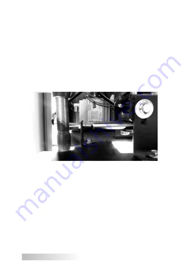
part of the furnace. The grate is positioned with a position control sensor (Hall
effect sensor, see Fig. 3, Fig. 6 and Fig. 7).
Figure 3
Moving grate positioning sensor (Hall effect sensor ).
NOTE:
Correct operation of the moving grate mechanism requires a correct setting of
the Hall effect sensor. A distance between the position sensor and the wrapping
connector of the moving grate should be 3 to 5 mm, these components should be
aligned axially.
The fuel feeder design developed at ZMK SAS, using a set of two screws,
is protected by an application No. W.120870 issued by the Polish Patent Of-
fice.
Additionally, for easier operation the boiler is equipped with a ceramic heater,
firing fuel during the boiler start-up (fuel self-firing). An automatic fuel firing and a
system to maintain flame after the set temperature is reached ensures an efficient
operation of this boiler even during periods of low demand for heat (an option
for continuous operation or operation with a domestic hot water tank during the
summer).


