


SARK
SARK
SARK
SARK-
-
-
-110
110
110
110
User’s Manual
Rev 1.2.6 October 3
rd
, 2015
- 7 -
© Melchor Varela – EA4FRB 2011-2015
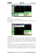
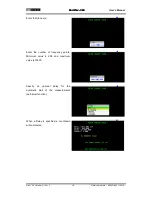
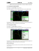
4 Operating the SARK-110
This chapter provides information about the SARK-110’s basic functionality and user interface.
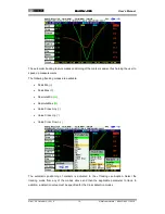
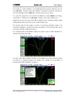
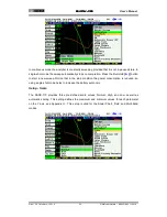
4.1 Screen Layout
The following figure shows the screen layout in Scalar Chart mode. It shows diagram areas that
are the same for all operating modes of the SARK-110. Screen layouts that show specifics for
each operating mode are provided in corresponding sections of this manual.
1
Diagram
11
Markers information
2
Traces
12
Detailed measurements
3
Markers
13
Frequency and span settings
4
Vertical axis labeling
14
Transmission Line length setting
5
Horizontal axis labeling
15
Reference impedance setting
6
Main menu
16
Loaded data file name
7
Highlighted menu option
17
Disk write operation in progress
8
Submenu
18
Calibration status
9
Highlighted submenu option
19
Run/Hold status
10
Currently selected submenu option
20
USB/Battery status


