background image

CAMERA OPERATION

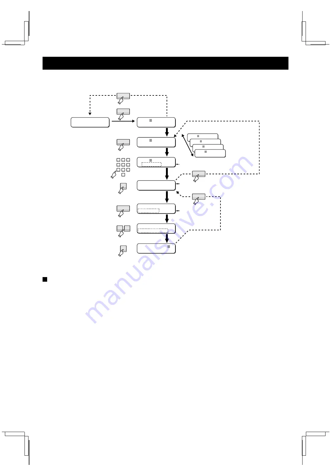
[B] Operation using the call-up commands

Use the procedure outlined below to operate the dome cameras.

Operating procedure

1. Press the INDIVIDUAL button.
2. Press the MODE button to change the displayed device to

CM”.

3. Enter the address with the numeric keypad.
4. Press the ENTER button to check the address.

The operating status of the camera appears in the menu
screen.

5. Press the FUNCTION button to bring up the commands.

The command name is displayed flashing.

For an explanation of the camera call-up commands, refer
to the Call-up command operation list on page 33.

6. Press the + (or – ) button to select the desired command.
7. Press the ENTER button to execute the command.

To abort the operation, press the STOP button.

C M : - -

1

    P T Z C A M 0 1

M X : - -

-

S A N Y O   C o n t r o l l e r
        1 5 : 3 0 : 3 0

C M : 0 0 1
E L S : o n     B L C : o f f

C M : 0 0 1
L - L   P H A S E

C M : 0 0 1
P R E S E T   M E M O R Y

1 Device display

C M : - -

-

2 Device selection

3 Address entry

4 Address check

5 Call-up command

6 Command selection

7 Command execution

3

4

5

6

7

8

9

0

INDIVIDUAL

MODE

FUNCTION

1

2

Operating status

Call-up command

CLEAR

CLEAR

CLEAR

+

Device title (

 P13)

ENTER

ENTER

Multiplexer

Timelapse VCR

Camera

Digital video
recorder

M X : - -

-

V R : - -

-

C M : - -

-

D R : - -

-

C M : 0 0 1     N o . - -

-

P R E S E T   M E M O R Y

L8CSB/XE (VSP-8000 GB) 2002. 4. 4

32

Summary of Contents for VSP-8000

Page 1: ...VSP 8000 About this manual Before installing and using this unit please read this manual carefully Be sure to keep it handy for later reference This manual gives basic connections and operating instructions XE L8CSB XE VSP 8000 GB 2002 4 4 ...

Page 2: ...ject to strong vibrations Avoid moving the system controller between cold and hot locations Do not place the system controller directly on top of a monitor TV as this may cause playback or recording problems Avoiding Electrical Shock and Fire Do not handle the power cord with wet hands Do not pull on the power cord when disconnecting it from an AC wall outlet Grasp it by the plug If any liquid is ...

Page 3: ...ified device to the VSP 8000 and download it collectively to other devices Transfer date time information You can download to a device that will use the data for the date time specified with the VSP 8000 and specify a date time collectively Alarm buzzer The controller will sound a built in buzzer when certain conditions arise such as a triggered alarm for a connected device or a change of operatio...

Page 4: ...entered G MENU button P7 Press to bring up the menus Switches between the menu display and initial display each time pressed H AF button Press to focus the camera automatically with a single button press I ZOOM lever Use to carry out electronic zooming J ENTER button Press to enter and finalize the settings K Joystick lever Tilt up down and to the left and right to move the cursor Used to carry ou...

Page 5: ... D Sub cable sold separately so that the system controller can be controlled using a computer Since this port is normally covered remove the cover before connecting 6 ADDRESS TERMINATE switch P6 Used to set the VSP 8000 for addressing or termination 7 Battery compartment Backup function The VSP 8000 is equipped with a lithium battery for backing up the internal clock of the unit The battery is cha...

Page 6: ...nd the B terminal to A Connecting using the push lock terminal Make the connections with a twisted pair cable Connect the A signals together and the B signals together To wall socket Twisted pair cable sold separately Twisted pair cable sold separately Digital video recorder sold separately Television monitor sold separately Monitor 1 sold separately Monitor 2 sold separately Multiplexer sold sepa...

Page 7: ...TE 1 2 3 1 0 ADDRESS TERMINATE 1 2 3 1 0 ADDRESS TERMINATE 1 2 3 1 0 1 0 TERMINATE Digital video recorder 2 Digital video recorder Setting the address When connecting multiple VSP 8000s assign the address switches 1 to 3 and termination for each unit on its rear panel The address can be set from 0 to 4 for each unit If the address for a unit is set to 0 then that unit becomes the master controller...

Page 8: ...g the Group Settings Y M D 0 0 C O D E M X S A N Y O C o n t r o l l e r S U M M E R T I M E N O U S E B A U D R A T E S E T 1 9 2 0 0 b p s G R O U P C H E C K O K E N T E R N O C L R C L O C K S E T S U M M E R T I M E S E T D A Y L I G H T T I M E S E C U R I T Y L O C K B A U D R A T E S E T T I T L E S E T G R O U P C H E C K MENU MENU ENTER ENTER ENTER ENTER ENTER ENTER P15 Setting the Buzze...

Page 9: ...h of May press 0 5 The clock is a 24 hour clock Ex To enter 9 00 p m 21 00 press 2 1 For mistakes Either press the joystick lever J or q to move the cursor or press the CLEAR button Then recheck and enter the correct setting 3 Press the ENTER button The settings are stored and the CLOCK SET screen reappears Press the MENU button to return to the initial screen Note To abort the setting press the M...

Page 10: ...AT and then press the joystick lever q to move the cursor to the right The display will change from SUN MON TUE WED THU FRI SAT SUN each time the or button is pressed 3 As in 2 set the start month default 03 and the start time default 03 The month will change from 01 02 03 11 12 01 each time the or button is pressed The hour will change from 01 02 03 21 22 01 each time the or button is pressed The...

Page 11: ... code is entered Also the lock will be released when the secret code is entered To return to the initial screen without releasing the lock please press the CLEAR button or the MENU button Deactivating the lock 1 Press any button on the operation panel The secret code entry screen appears 2 Enter the secret code with the numeric keypad The lock is deactivated Note To reset the security lock or time...

Page 12: ...lever J or q to move the cursor and then recheck and then enter the correct setting 6 Press the ENTER button The initial screen reappears and the timer lock will activate at the set time C O D E ENTER C O D E 1 2 3 4 1 2 3 4 5 6 7 8 9 0 C O D E 1 2 3 4 T I M E R N O U S E ENTER C O D E 1 2 3 4 T I M E R U S E C O D E 1 2 3 4 O N 0 0 0 0 O F F 0 0 0 0 ENTER 1 2 3 4 5 6 7 8 9 0 C O D E 1 2 3 4 O N 1...

Page 13: ...ton to select the desired communication speed baud rate The display will change from 19200 2400 4800 9600 19200 units bps each time pressed 3 Press the ENTER button Set the baud rate to return to the BAUD RATE SET screen Press the MENU button to return to the initial screen B A U D R A T E S E T 1 9 2 0 0 b p s Flashing ENTER ENTER MENU Note Communications will be interrupted if the baud rate chan...

Page 14: ...phanumeric characters and symbols 1 Press 7 five times for S and then press the joystick lever q to move the cursor to the right 2 Press 3 three times for E and then press the joystick lever q to move the cursor to the right 3 Press 8 two times for T and then press the joystick lever q to move the cursor to the right 4 Press 1 once for 1 Numeric key Title display Numeric key Title display 1 3 __ 3...

Page 15: ...screen 2 Press the ENTER button Performs the group check During the check the cursor will move to the right When the group check is completed the data gathered is stored in memory and the GROUP CHECK screen reappears Press the MENU button to return to the initial screen Note If group settings were changed at another controller always perform the group check and save the group settings If a device ...

Page 16: ...ress the or button to change the KEY IN setting to ON and then press the ENTER button The setting changes in the order OFF ON OFF each time a button is pressed To leave the buzzer setting unchanged simply press the ENTER button The CAUTION setting will then flash For mistakes Press the CLEAR button to return to the previous setting item 4 To make the buzzer sound press the or button to change the ...

Page 17: ...R to upload menu data from The display will change from MX multiplexer VR timelapse VCR CM camera DR digital video recorder MX each time pressed Note The device selected here will be stored in the memory and next time that selected device will be displayed first in the device selection item 3 Enter the address e g 13 with the numeric keypad 4 Press the ENTER button M UPLOAD appears and then the da...

Page 18: ... VCRs in Group 1 3 Press the ENTER button M DOWNLOAD appears and then the menu data is downloaded to the timelapse VCRs in Group 1 Press the CLEAR button to cancel the download 4 When Complete appears the download is finished Press the MENU button to return to the initial screen V R A L L O K E N T E R N O C L R G R 1 2 3 4 5 6 7 8 9 0 G R 0 1 O K E N T E R N O C L R G R 0 1 M D O W N L O A D ENTE...

Page 19: ...ess the ENTER button Date and time data is downloaded to all devices the display CLOCK DOWN LOAD will return If you press the CLEAR button the display returns to the date display Press the MENU button to return to the initial screen B Downloading to a specified group 1 Press the MENU button Then press the or button until CLOCK DOWN LOAD is displayed and press the ENTER button The system controller...

Page 20: ...er returns to download standby mode 6 Press the ENTER button Date and time data is downloaded to devices of Group 1 the display CLOCK DOWN LOAD will return If you press the CLEAR button the display returns to the date display Press the MENU button to return to the initial screen 0 1 0 4 2 5 O K E N T E R N O C L R ENTER 1 5 0 0 0 2 O K E N T E R N O C L R ENTER C L O C K D O W N L O A D ENTER L8CS...

Page 21: ...en full screen L QUAD Live picture mode quad screen L QUAD S Live picture mode quad screen sequential display L PLUS 16 Live picture mode plus screen 16 screen full screen L PLUS S Live picture mode plus screen sequential display L FULL S Live picture mode full screen sequential display L FULL 16 Live picture mode 16 channel full screen M2SET 16 1 16 channel full screen for monitor 2 M2SET S 1 Seq...

Page 22: ...e matrix switcher function are connected at the same time in a group operation the equipment will behave differently when the MON2 SPOT button is operated The command display in the menu screen section will appear only on MON2 Operations A Switches the channel of the monitor 1 plus screen 1 Press the PLUS button Press the PLUS button again to cancel 2 Press the FULL button 3 Specify the channel wi...

Page 23: ...iplexer MX 001 PW OFF POWER ON Turns on multiplexer MX 001 PW ON S LOCK OFF Deactivates the security lock MX 001 S L OFF S LOCK ON Activates the security lock MX 001 S L ON ZOOM Zooms image in one screen of monitor 1 main monitor MX 001 ZOOM For models without a password type security lock function Note If the connected device does not have command functions then No OPE will appear in the menu scr...

Page 24: ...ing on the camera selected A If a camera not manufactured by Sanyo is selected P24 B If camera control is not possible 24 C If camera control permission is refused 24 6 Remotely operate cameras with the CAMERA command buttons For an explanation of the camera command buttons refer to the Command button operation list on page 30 of the Camera Operation section 30 Note When using camera control with ...

Page 25: ...ppear in the display if the selected camera is not manufactured by Sanyo Pressing command buttons of the CAMERA keypad will not change display of this message B If camera control is not possible UN CON will appear in the display if camera control is not possible due to automatic switching of the selected monitor or an active alarm condition Please refer to Switching the camera to be controlled C I...

Page 26: ...layed Status Description Status Description Status Description C OUT OF Eject cassette during standby PLAY Playing back STBY Standby COUT C OUT ON Eject cassette R F ADV Reverse advancing STL STILL Pausing CUE Cueing REC Recording STOP Stopped F ADV Forward advancing REW Rewinding TSTB TM STBY Timer recording standby FF Fast forwarding RPLY RVS PLAY Reverse playing back T M CHK Tape manageme nt ch...

Page 27: ...e cursor to the right in the menu screen also moves date time screen the to right Joystick lever t Cancels confirmation of the menu screen VR 001 DOWN Returns display to previous menu Moves the cursor downward in the menu screen may not be applicable with some devices also moves display of date and time downward Moves the cursor downward in the menu screen may not be applicable on some models Edit...

Page 28: ...commands refer to the Call up command operation list on page 28 6 Press the or button to select the desired command 7 Press the ENTER button to execute the command To abort the operation press the STOP button V R 1 3 R D F L O O R M X S A N Y O C o n t r o l l e r 1 5 3 0 3 0 V R 0 0 1 P W O F F V R 0 0 1 S T O P 2 4 H V R 0 0 1 A L A R M S E A R C H V R 0 0 1 P O W E R O F F 1 Device display V R ...

Page 29: ...ll appear in the menu screen In group operation the commands with the cannot be performed Operations A Plays back first 5 seconds of alarm recordings 1 With the tape stopped press the FUNCTION button 2 Press the or button to select ALARM SCAN 3 Press the ENTER button 4 Press the FF button B Searches for specified alarm recording and still image 1 With the tape stopped press the FUNCTION button 2 P...

Page 30: ...tion of the camera command buttons refer to the Command button operation list on page 30 Checking the address When the address is checked in step 4 the on or off status of the electronic zoom ZOOM electronic sensitivity boost ELS and glare compensation are displayed in the menu screen IRIS M X S A N Y O C o n t r o l l e r 1 5 3 0 3 0 C M INDIVIDUAL 1 Device display C M C M 1 4 T H F L O O R 2 Dev...

Page 31: ...Mcon Pans to left when electronic zoom is on Joystick lever s Changes set value at menu screen CM 001 UP CM 001 CAMcon Tilts upward when electronic zoom is on Joystick lever q Changes set value at menu screen CM 001 RIGHT CM 001 CAMcon Pans to right when electronic zoom is on Joystick lever t Changes set value at menu screen CM 001 DOWN CM 001 CAMcon Tilts downward when electronic zoom is on ENTER...

Page 32: ...hutter speed to one of four speeds 1 60 1 100 1 500 or 1 2000 If more than four speed settings are available the following display will appear Shutter speed of 1 50 or slower than 1 60 SLOW Shutter speed of 1 50 or 1 60 OFF Shutter speed of 1 100 or 1 120 FL flickerless Shutter speed of 1 100 or faster than 1 120 FAST 1 Press the ELS button 2 Press the button to set the shutter speed If you press ...

Page 33: ...l up command operation list on page 33 6 Press the or button to select the desired command 7 Press the ENTER button to execute the command To abort the operation press the STOP button C M 1 P T Z C A M 0 1 M X S A N Y O C o n t r o l l e r 1 5 3 0 3 0 C M 0 0 1 E L S o n B L C o f f C M 0 0 1 L L P H A S E C M 0 0 1 P R E S E T M E M O R Y 1 Device display C M 2 Device selection 3 Address entry 4 ...

Page 34: ... A L L PHASE Adjusts the vertical synchronization 1 Press the or button to select L L PHASE 2 Press the ENTER button 3 Press and hold the or button to adjust the vertical synchronization 4 Press the CLEAR button B PRESET MEMORY Records the filming position zoom and focus for a position number 1 Press the or button to select PRESET MEMORY 2 Press the ENTER button 3 Use the joystick lever to adjust ...

Page 35: ...Status Description Status Description D PLAY Playing back the archive recording area AL FULL Alarm recording area full N PLAY Playing back the normal recording area PRE REC Pre alarm recording is set A PLAY Playing back the alarm recording area PLAY Playing back D REC Recording in the archive recording area T STBY Timer recording standby N REC Recording in the normal recording area N R STOP Record...

Page 36: ...lay menu REC a Performs recording DR 001 REC OK OK ENTER NO CLR REC STOP Stops recording DR 001 R STP OK OK ENTER NO CLR SEARCH FR FI Displays search setting menu during recording or still image DR 001 SEARCH Switches frame field display during playback PLAY SPEED l Decreases menu screen settings and playback speed DR 001 SPD DN PLAY SPEED j Increases menu screen settings and playback speed DR 001...

Page 37: ...of the digital video recorder call up commands refer to the Call up command operation list on page 37 6 Press the or button to select the desired command 7 Press the ENTER button to execute the command D R 2 3 D R 2 3 M X S A N Y O C o n t r o l l e r 1 5 3 0 3 0 D R 0 0 1 C L K A D J D R 0 0 1 P S T O P R S T O P D R 0 0 1 C O P Y D R 0 0 1 C L K A D J P R E S S E N T E R 1 Device display D R 2 D...

Page 38: ... lever to make copy settings Press the CLEAR button and return to the call up command selection display C TIMER ON OFF Sets a recording program on the menu screen Please refer to the digital video recorder instruction manual 1 Press the or button to select TIMER ON OFF 2 Press the ENTER button and return the menu screen to its normal screen Recording is programmed 3 Press the or button to select T...

Page 39: ...UP GROUP G R 0 1 S E T V R G R 0 1 C H E C K V R 0 0 1 0 0 2 0 0 3 G R 0 1 C H E C K V R 0 0 4 0 0 6 Checking the address assignment ENTER Operating procedure 1 Press the GROUP button while holding down the ENTER button Enters the setting mode 2 Press the MODE button to select the type of device the address is that will be assigned 3 Press the or button to select the group number 4 Enter the addre...

Page 40: ...ss the ENTER button 2 Enter 0 0 2 with the numeric keypad and press the ENTER button 3 Using the same procedure enter the addresses 3 to 5 4 Press the CLEAR button twice The initial screen reappears 5 When two or more VSP 8000s are connected together perform group checks with the other controllers P14 VR 001 MX 001 CM 001 VR 003 MX 003 MX 002 VR 002 CM 002 DR 002 VR 001 VR 002 VR 003 VR 004 VR 005...

Page 41: ...CKING V LOCK REC PLAY SPEED EJECT Operating procedure 1 Press the GROUP button Enter the group mode 2 Using the numeric keypad specify a group number 3 Press the ENTER button to check the group number If there is no group registered at that number unregistered will appear 4 Press the MODE button to select the devices for group operation To operate all devices select ALL Note Even if you select ALL...

Page 42: ... 001 CM 001 VR 003 MX 003 VR 002 CM 002 DR 002 VR 001 VR 002 VR 003 VR 004 VR 005 CM 003 CM 016 MX Multiplexer VR Timelapse VCR CM Camera DR Digital video recorder MX 001 CM 001 CM 002 Group 1 Group 2 Group 3 Group 15 Controller 1 Controller 4 Controller 0 Simultaneous playback MX 002 GROUP G R 3 G R 3 G R 0 3 M X C o m m a n d r e a d y ENTER MODE G R 0 3 V R C o m m a n d r e a d y G R 0 3 P L A...

Page 43: ...ce type If four or more addresses exist within the group then scroll with the or button 2 Press the GROUP button Return to the setting mode G R 0 1 C L E A R M X 0 0 1 S A N Y O C o n t r o l l e r 1 6 2 0 1 5 CLEAR CLEAR 1 Deletion mode G R 0 1 C L E A R V R 0 0 1 2 Device selection G R 0 2 C L E A R V R 0 0 1 G R 0 3 C L E A R V R 0 0 1 0 0 2 0 0 3 G R 1 5 C L E A R V R u n r e g i s t e r e d 3...

Page 44: ... or buttons 2 Date and time of alarm 3 Device where alarm occurred 4 Channel of alarm 5 Type of alarm EA external alarm VL Video loss SA Sensor alarm 6 Alarm recording start and end The alarm recording start IN and end OUT are entered in the alarm list as two different events IN Alarm recording start OUT Alarm recording end Note Dome cameras are not equipped with an alarm function A 0 9 8 1 1 3 0 ...

Page 45: ...manual for details Example status list 1 Status number The higher the number the newer the status change The status number can be changed with the or buttons 2 Date and time of status change 3 Device where status change occurred VR Timelapse VCR CM Camera DR Digital video recorder 4 Status that changed S 0 0 5 1 1 1 5 1 5 3 0 V R 0 0 1 P L A Y 1 3 4 2 Note The status list can be set at some connec...

Page 46: ...te lock at master controller 10 No ADR Address does not exist e g has not been set Recheck and enter correct address 38 NO ALARM Alarm list has no alarm entries Check alarm list after ALARM lamp flashes 43 NO CHANGE Status list has no status entries Check status list after STATUS lamp flashes 44 unregistered Device is not registered in a group Either specify that device or register it in a group 4...

Page 47: ...ers 5 devices Multiplexers timelapse VCRs cameras and digital video recorder 128 devices each Dome type cameras 64 devices Ambient conditions Temperature 0 to 40 C Relative humidity 80 or less Storage conditions Temperature 20 to 60 C Relative humidity 80 or less Power supply 12 V DC Power consumption 4 W External dimensions 375 W x 55 H x 165 D mm Weight 1 5 kg Accessories AC adapter 1 modular ca...

Page 48: ...SANYO Electric Co Ltd 1AC6P1P2442 L8CSB XE 0402KP SY Printed in Japan L8CSB XE VSP 8000 GB 2002 4 4 ...

Reviews: