background image

Depending on the conditions of use,
installation and environment, please be sure
to make the appropriate settings and
adjustments. If you need help with installation
and/or settings, please consult your dealer.

CONTENTS

INFORMATION TO USER ..................................2

PRECAUTIONS...................................................3

PARTS NAMES...................................................4

MOUNTING THE LENS ......................................7

CONNECTIONS ..................................................9

SETTINGS.........................................................10

USING THE ON-SCREEN MENUS .................... 13

ADJUSTMENTS................................................14

TROUBLESHOOTING.......................................26

MENU DISPLAY...............................................27

SPECIFICATIONS .............................................29
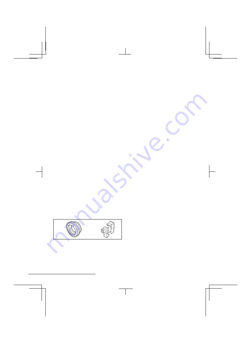
ACCESSORIES

1

C mount adaptor (5 mm).....................1 pc.

The C mount adaptor must be used to be
able to install a C mount lens on the
camera.

2

Lens iris plug (4-pin) .............................1 pc.

1

2

FEATURES

Built-in interline transfer method 1/3" CCD,
approx. 410,000 picture elements

Low smear, anti-blooming, low lag, no
burning and no geometric distortion using
the CCD solid state image device.

100% solid state components giving
excellent immunity to shock and vibration

Not subject to interference from magnetic
or electrostatic fields

High sensitivity, minimum required
illumination is 0.9 lux (F1.2, AGC Gain:
High, incandescent lighting)

Horizontal resolution, more than 470 TV
lines

Power supply: 24 V AC operation

L53P4/US  GB  1998, 3, 11

English

 1

Summary of Contents for VCC-5974

Page 1: ...INSTRUCTION MANUAL COLOR CCD Camera VCC 5974 About this manual Before installing and using the camera please read this manual carefully Be sure to keep it handy for later reference L53P4 US GB 1998 3 11 ...

Page 2: ......

Page 3: ...C mount adaptor must be used to be able to install a C mount lens on the camera 2 Lens iris plug 4 pin 1 pc 1 2 FEATURES Built in interline transfer method 1 3 CCD approx 410 000 picture elements Low smear anti blooming low lag no burning and no geometric distortion using the CCD solid state image device 100 solid state components giving excellent immunity to shock and vibration Not subject to int...

Page 4: ...equency energy and if not installed and used in accordance with the instructions may cause harmful interference to radio communications However there is no guarantee that interference will not occur in a particular installation If this equipment does cause harmful interference to radio or television reception which can be determined by turning the equipment off and on the user is encouraged to try...

Page 5: ...r audio speakers the magnetic field they generate will distort the image Protect from humidity and dust To prevent damages to the camera do not install it where there is greasy smoke or steam where the dampness may get too high or where there is a lot of dust Protect from high temperatures Do not install close to stoves or other heat generating devices such as spotlights etc or where it could be s...

Page 6: ... Press this button to move the cursor down 5 Flange back lock screw FLANGE BACK LOCK 6 Flange back adjustment screw FLANGE BACK ADJ 7 Lens mount cap The cap is installed to protect the lens mount section Remove the lens mount cap before installing a lens sold separately 8 Camera installation bracket The bracket can be fixed at the top or bottom of the camera When fixing the bracket be sure to use ...

Page 7: ... 60 sec b Internal Line lock switch SYNC INT c Auto gain control switch AGC ON d White balance switch WB all ON ATW e Backlight compensation switch BLC ON f Electronic iris EI Auto iris AI switch AI g Auto iris lens switch A I LENS DC Notes When using a 1 2 or 2 3 inch C mount VIDEO with EE internal amplifier auto iris type lens set the A I LENS switch to the VIDEO position The settings entered in...

Page 8: ...tor POWER Comes on when the power to the camera is on I 24 V AC input terminal 24 V AC GND With this camera use only the 24 V AC power adaptor model No VPT 115 available from Sanyo Power supply connections Use a 3 wire grounded cable 22 AWG or more and connect as shown by the illustration CAUTION To prevent camera and or AC adaptor failure pay close attention to polarity when making the connection...

Page 9: ...E BACK ADJ screw 3 Repeat steps 2 and 3 until the image stays in focus when changing from a telephoto shot to a wide angle shot When the setting is complete tighten the FLANGE BACK LOCK screw MOUNTING THE LENS Check the lens mount Do not use a lens if the length L is more than 5 mm That may damage the camera and prevent proper installation Installation of a DC type auto iris lens sold separately A...

Page 10: ...the supplied plug as indicated When using lenses from other makers make sure that the pins connections in the plug correspond to the ones of the camera Refer to the lens specifications to check the pins connections in the plug If they are different than indicated remove the original plug and connect the supplied plug according to the diagram 4 Set the A I LENS switch in the camera setup section to...

Page 11: ...sing to correct CONNECTIONS Basic connection for monitoring or recording The peripheral devices VCR monitor lens etc and cables are sold separately 1 Make the video signal connection between the camera and the monitor or time lapse VCR 2 Insert the plug of this power cord into a wall outlet The POWER indicator A will light Adjust the picture on the monitor using the Brightness and Contrast control...

Page 12: ...e speed setting switches 1 2 and 3 for the high speed electronic shutter are all set to the OFF position This sets the electronic shutter speed to 1 60 sec The three switches in the camera setup section can be set as indicated in table A to select one of the 8 speeds available Notes When using the high speed electronic shutter the BLC switch must be set to the OFF position Using the high speed ele...

Page 13: ...ns of use the white balance mode can be set using the two WB switches 7 and 8 in the camera setup section see table 1 ATW Initial setting The initial value cannot be changed LOCK The white balance is done automatically while the AWB LOCK button is pressed then it is locked when the button is released PRESET The white balance is done according to one of the three preset modes The preset modes can b...

Page 14: ... 3 and the lens iris is set automatically so that the backlight correction is optimum for the section composed of windows W 1 and 2 This setting is recommended when the subject will be centred in the image MANUAL 1 or MANUAL 2 Fig 1 3 The size and position of window W 4 and the windows W 0 4 distribution WINDOW WEIGHTING can be set manually to control a bigger area of the screen e g when the subje...

Page 15: ...d value or setting then press the SET button 3 Initial values protection WRITE PROTECT ON Default setting The initial values cannot be modified OFF Press the CURSOR d or c button to select OFF then press the SET button The write protection is cancelled and the initial values can then be changed 4 To exit the menu Press the CURSOR j or l button to select END get it flashing then press the SET butto...

Page 16: ...elect OFF then press the SET button CONTENTS OF ADJUSTMENTS 1 SYNC 1 1 V sync phase adjustment 15 1 2 VBS phase adjustment 16 2 IRIS 2 1 Auto iris level adjustment 17 3 BLC 3 1 Setting the light measuring area characteristics size position and distribution for the MANUAL 1 setting 18 3 2 BLC level adjustment for the PRESET 1 setting 20 4 WHITE BALANCE 4 1 PRESET MODE 2 indoors fluorescent lighting...

Page 17: ...is obtained The on screen marker b will move and the adjustment value will flash according to the vertical sync phase setting Note When an adjustment is made the PRESET setting will automatically switch to OFF To return to the initial value just return the PRESET setting to ON then press the SET button 3 When finished 1 Press the CURSOR j or l button to select END get it flashing then press the SE...

Page 18: ...H press the CURSOR l button to select the sub carrier SC phase 3 Press the CURSOR d or c button to adjust the sub carrier SC phase The on screen marker b will move and the adjustment value will flash according to the sub carrier phase setting Note When an adjustment is made the PRESET setting will automatically switch to OFF To return to the initial values just return the PRESET setting to ON then...

Page 19: ...hen an adjustment is made the PRESET setting will automatically switch to OFF To return to the initial value just return the PRESET setting to ON then press the SET button 3 When finished Refer to step 3 on page 15 Notes If IRIS is set to EI electronic iris mode the SHUTTER setting function will not operate When the AGC switch is set to OFF the IRIS cannot be set to EI MENU FOR ADJUSTMENT SYNC INT...

Page 20: ...s selected then press the SET button The adjustment sub menu SIZE will be displayed 3 Press the CURSOR buttons to set the size of the area then press the SET button The adjustment sub menu POSITION will be displayed 4 Press the CURSOR buttons to move up down right left the area to the desired position then press the SET button The adjustment sub menu WINDOW WEIGHTING will be displayed Note The WIN...

Page 21: ...F To return to the initial value just return the PRESET setting to ON then press the SET button 6 When finished Refer to step 3 on page 15 WINDOW WEIGHTING W0 5 W1 1 W2 3 W3 3 W4 FIX 15 PRESET OFF END MENU CURSOR CURSOR CURSOR CURSOR CURSOR 1_2_3_4_5 3_4_5 6_7_8_9_10 WINDOW WEIGHTING W0 5 W1 5 W2 10 W3 3 W4 FIX 15 PRESET OFF END MENU CURSOR CURSOR 8_9_10 WINDOW WEIGHTING W0 5 W1 5 W2 10 W3 10 W4 F...

Page 22: ...lash according to the BLC level setting Note When an adjustment is made the PRESET setting will automatically switch to OFF To return to the initial value just return the PRESET setting to ON then press the SET button 5 When finished Refer to step 3 on page 15 Note The BLC level adjustments should be entered under the PRESET 1 or MANUAL 1 settings The BLC level adjustments entered under the PRESET...

Page 23: ...lash according to the red offset setting When finished setting the red offset press the CURSOR l button to select B blue Press the CURSOR d or c button to adjust the B blue offset The on screen marker b will move and the adjustment value will flash according to the blue offset setting Note When an adjustment is made the PRESET setting will automatically switch to OFF To return to the initial value...

Page 24: ......

Page 25: ......

Page 26: ...the desired camera ID maximum of 6 characters or symbols Note The symbol c indicates a blank space When entered in a camera ID it will be displayed as a blank space 5 When finished entering the camera ID Press the CURSOR d or c button to select MENU get it flashing then press the SET button to return to the MENU FOR ADJUSTMENT display 6 To correct the entered camera ID repeat steps 2 to 5 7 When f...

Page 27: ...ancelled and you cannot return from this display to the menu display This happens even if the PRESET setting is set to ON To return to the camera display use the CURSOR buttons to select END get it flashing then press the SET button A higher setting value will give a sharp pictures a lower setting value will give a soft pictures Note When an adjustment is made the PRESET setting will automatically...

Page 28: ...ing a DC type lens the CORSOR button should be adjusted B When using a VIDEO type lens the LEVEL volume on the lens should be adjusted The picture is not clear Is the monitor correctly adjusted Is the flange back position correctly set Is the lens focus correctly adjusted Are the lens surfaces clean If there is dust or finger prints on the lens the image quality will deteriorate To clean the lens ...

Page 29: ...insert VBS signal insert VS signal b IRIS ADJUSTMENT SW10 AI EI AI b BLC ADJUSTMENT SW9 ON OFF ON b WHITE BALANCE SETTING SW7 8 all ON ATW ON OFF OFF ON all OFF ON ON ON ON ON OFF ON OFF ON ON OFF OFF OFF ON ON OFF ON OFF OFF OFF ON ADJUSTMENT FOR WB GAIN R o z p 86 B o z p 72 OFF b AGC SETTING SW6 ON OFF ON b SHUTTER SETTING SW1 2 3 all OFF 1 60 sec 60 OFF b CAMERA ID SETTING CURSOR button ON OFF...

Page 30: ...W4 FIX 15 MODE2 MODE3 MODE2 MODE3 ADJUSTMENT FOR BLC BLC LEVEL o z p 15 ADJUSTMENT FOR APERTURE o z p 6 CAMERA ID SETTING CAMERA ID IS CAMERA ID SETTING ABCDEFGHIJKLM NOPQRSTUVWXYZ 0123456789 p MENU CAMERA ID IS ADJUSTMENT FOR BLC SIZE ADJUSTMENT FOR BLC POSITION OFFSET R z p 0 B o z p 255 OFFSET R o z p 29 B o z p 189 OFFSET R z p 7 B o z p 255 GAMMA OFF AGC GAIN NORMAL HIGH HIGH GAMMA ON AGC GAI...

Page 31: ...ion Manual ON OFF switching Active zone light measuring system Active when using an auto iris lens Iris function Manual Electric iris EI Auto iris AI switching Electronic iris range 2 lux to 100 000 lux F 1 2 lens 2 7 lux to 130 000 lux F 1 4 lens Electronic shutter 8 speeds selectable by switches 1 60 1 100 1 250 1 500 1 1000 1 2000 1 4000 1 10000 sec Flange back 12 5 mm 0 5 mm White balance ATW ...

Reviews: