-19-
■
LCD Panel/Prism Ass’y Replacement
IMPORTANT NOTICE on LCD Panel/Prism Ass'y Replacement
LCD panels used for this model can not be replaced separately. Do not disassemble the LCD Panel/Prism Ass’y.
These LCD panels are installed with precision at the factory. When replacing the LCD panel, should be replaced
whole of the LCD panels and prism ass’y at once.
After replacing LCD Panel/Prism ass’y, please check the following points.
- Check that there is no color shading at the top, bottom, left or right of the screen. If there is, try to
remove the shading following to the chapter “Optical Adjustment”.
- Check the white balance. If it needs the adjustment, adjust the white balance following to the “White
Balance Adjustment” and “Common Centre Adjustment” in the chapter “Electrical Adjustment”.
- Check the white uniformity on the screen.
If you find the color shading at the some part of the screen, it needs to take the color shading adjust-
ment. This adjustment should be performed by a computer and it also requires a special software
“Color Shading Correction”. The software will be supplied separately and can be ordered as follows;
COLOR SHADING CORRECTION Ver. 3.0
Service Parts No.
645 056 6288
1
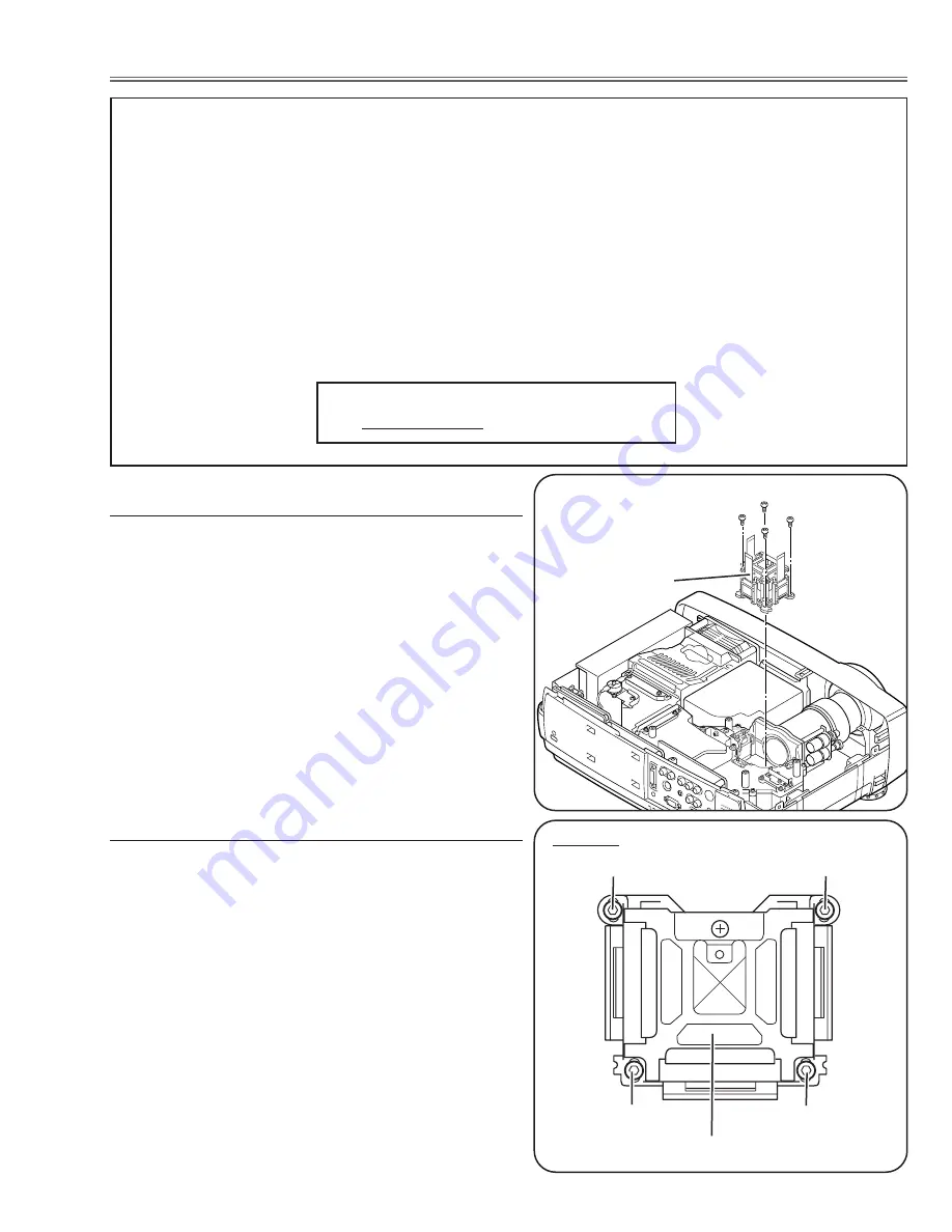
Remove the cabinet top and main board following to
“Mechanical Disassemblies”.
2
Remove 4 screws by using the 2.0 mm hex driver and
take the LCD Panel/Prism ass’y off upward from the
optical unit.
After replacing or installing the LCD Panel/Prism ass'y,
please make sure to obtain the best focus in both TELE
and WIDE zoom. If the focus adjustment is required,
please adjust the positioning of LCD Panel/Prism Ass’y by
following below procedure.
Mounting Procedure:
1
Loosen 4 screws
A
on the LCD Panel/Prism ass'y with
2.0 mm hex driver.
2
Turn the projector on and project the image with WIDE
zoom, and adjust the FOCUS control to obtain the best
focus.
3
Turn the ZOOM control to the TELE position.
4
Move the LCD Panel/Prism Ass’y backward or forward
(about 0mm ~ 0.8mm) to obtain the proper focus.
Confirm the focus at TELE and WIDE zoom.
5
Tighten 4 screws
A
to fix the LCD Panel/Prism ass'y.
Top View
A
A
A
A
LCD Panel/Prism Ass’y
LCD Panel/Prism Ass’y removal
Note on LCD Panel/Prism Ass’y Mounting
LCD Panel/Prism
Ass’y
Note:
Do not replace the LCD
panel separately otherwise
it can not obtain proper pic-
ture.
Summary of Contents for PLC-XU40
Page 50: ... 50 IC Block Diagrams AD8075 Selector IC201 AD8183ARU Selector IC1201 AN7513 Audio Amp IC5001 ...
Page 51: ... 51 AN5870SB RGB SW IC5201 IC Block Diagrams AD9884AKS A D IC8201 ...
Page 54: ... 54 IC Block Diagrams CXD3526GG LCD Driver Timing Generator IC401 FA5502 P F Control IC611 ...
Page 55: ... 55 LA7217 Sync Separator IC5361 M62392 D A IC3561 IC Block Diagrams ...
Page 56: ... 56 NJM2284M Switch IC2101 IC Block Diagrams M62393 D A IC281 IC7801 ...
Page 82: ...MA3 XU4000 Electrical Parts List 82 Key No Part No Description Key No Part No Description ...
Page 84: ...MA3 XU4000 84 47 44 44 47 44 44 Mechanical Parts List 47 57 56 47 47 Optical Parts ...
Page 85: ...MA3 XU4000 85 44 44 54 67 Red 68 Green 69 Blue 45 45 45 Mechanical Parts List ...
Page 87: ...MA3 XU4000 87 52 a 52 46 46 46 46 52 Mechanical Parts List ...
Page 88: ...MA3 XU4000 88 Mechanical Parts List 58 70 63 71 57 60 65 59 64 66 51 55 62 ...
Page 90: ... MA3A Jan 2003 BB 400 Printed in Japan SANYO Electric Co Ltd ...
Page 107: ...1 2 3 4 5 6 7 8 9 A B C D E F G H I J K L A10 15 Schematic Diagrams PLC XU40 A10 Left ...
Page 115: ...Diagrams Drawings MA3 XU4000 ...


