-14-
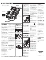
Mechanical Disassembly
v
Optical unit, MCI, Buzzer, Temp., Line Filter board,Fans removal
Fig.4
Temp. board
SP901
Projection lens
Noise filter
Optical unit
(T3x6)x
(T3x8)
(M.5x8)x4
(T3x8)x
(T3x6)
Line filter board
FN904
FN903
FN905
Buzzer board
Battery
(M3x10)
Duct bottom
1. Remove the Optical unit.
. Remove the MCI board.
3. Remove the Battery and Buzzer board.
3-1. Remove Screw (T3x8) and 4 hooks on the duct and then remove the
Duct.
3-. Remove the Duct top and then remove the Buzzer board.
4. Remove the Line filter board and Temp. board.
5. Remove fans and SP901.
Duct top
MCI board
(T3x8)x5
Summary of Contents for PLC-XU111
Page 62: ... 62 IC Block Diagrams BA7078 Sync Separator IC5301 AN5870 Signal Switch IC5201 ...
Page 63: ... 63 IC Block Diagrams FA5502 P F Control IC601 BA9743 DDC Control IC5751 ...
Page 64: ... 64 IC Block Diagrams HIN202EIB RS 232C Driver IC3801 FA7711 DC DC Converter IC5801 ...
Page 66: ... 66 IC Block Diagrams L3E01060 Level Shift IC2501 IC2531 IC2561 LM4889 Audio Output IC5031 ...
Page 67: ... 67 IC Block Diagrams NJW1141 Audio Control IC5001 M62334 DAC IC3501 ...
Page 68: ... 68 IC Block Diagrams PW190 Scaler IC301 STR Z2156 Power OSC IC651 ...
Page 69: ... 69 IC Block Diagrams TE7783 Parallel I O Expander IC1802 ...
Page 108: ... KM6AC May 2007 DC 350 Printed in Japan SANYO Electric Co Ltd ...


