-5-
Mechanical Disassembly
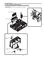
4-1. Filter Box Assy and Fans removal
1. Remove 4 screws-A (T3x8) and 1 screw-B(M3x6) and take the Filter Box
Assy upward off.
. Remove screws-C (T3x10) and pull the Fans Assy upward off.
A
A
Filter cartridge
Filter box assy
M3x8
M3x8
M3x8
t3x16
t3x8
t3x8
t3x8
t3x8
Wind sensor
(S901)
c
Filter motor
Filter SW board
Round sensor
board
FN905
FN904
B
Summary of Contents for PLC-XTC50AL
Page 99: ... 99 IC Block Diagrams ISL98001 A D Converter IC2201 L3E06170 S H IC501 IC531 IC561 ...
Page 100: ... 100 IC Block Diagrams M62393 DAC IC7971 L3E07111 LCD DRIVE DIGITAL GAMMA IC401 ...
Page 101: ... 101 IC Block Diagrams NJM2671 Motor Controller IC7601 LC87F2G08A MCU IC4501 ...
Page 102: ... 102 IC Block Diagrams PW392 Scaler IC301 PW610 Keystone IC2301 ...
Page 103: ... 103 IC Block Diagrams TE7783 I O Expander IC4801 TPA3123 Audio Output IC5051 ...
Page 104: ... 104 IC Block Diagrams UPC324GR Ope Amp IC1423 ...
Page 158: ... KH7AM Nov 2009 DC 200 Printed in Japan SANYO Electric Co Ltd ...


