


3
Ŷ
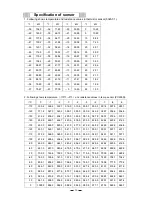
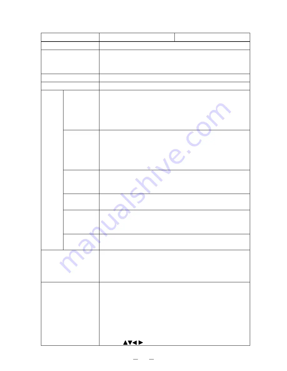
Control specifications
Item MDF-C2156VAN
MDF-C2156VANC
Cooling performance
Center of the chamber; -150
㷄䋨
AT30
㷄
, No load
䋩
Temp. controller
Micro-processor control system
Setting range; -125
㷄䌾
-155
㷄䋨
Unit;1
㷄䋩
Non-volatile memory
Temp. sensor
Platinum resistance; Pt.1000
ȍ
Temp. display
Digital display
High temp.
Setting range: +5
㷄
~+20
㷄
(Initial; +10
㷄
)
ALARM lamp and LCD display flashes, intermittent buzzer tone
with 15min. delay
Remote alarm contact: Normal Open, Rating; DC30V, 2A
Remote alarm contact activates with 15min delay
Low temp.
Setting range: -5
㷄
~-20
㷄
(Initial; -10
㷄
)
ALARM lamp and LCD display flashes, intermittent buzzer tone
with 15min. delay
Remote alarm contact: Normal Open, Rating; DC30V, 2A
Remote alarm contact activates with 15min delay
Door
When outer door is open, indication of ‘Door Open’ is shown.
ALARM lamp blinks and buzzer beeps intermittently after delay
time is passed.
Filter
ALARM lamp flashes, message indication and intermittent buzzer
tone emitted
Power failure
When the power to the unit is not connected or power failure,
ALARM lamp flashes and intermittent buzzer tone emitted
Remote alarm contact activates.
Alarm
Remote alarm
3P remote alarm terminal: DC30V, 2A, NC-COM, NO-COM
Temperature alarm turns on during power failure.
Display
LCD panel
Temperature display; Digital display (1
㷄
increment)
Internal temperature is displayed by graphics, 24hours record can
be displayed per screen.
Control panel
Lamp: BATTERY, ALARM, STANDBY
Buzzer key: BUZZER
Menu key: MENU
Clear key: CE
Entry key: ENT
Figure input key
LCD contrast adjusting knob: CONT
Shift key:
Summary of Contents for MDF-C2156VAN
Page 9: ...6 Dimensions ...
Page 11: ...8 Refrigeration circuits ...
Page 12: ...9 Refrigeration circuit welding points 䌅䌁㩷 䌅䌂㩷 䌅䌃㩷 䌅䌄㩷 䌅䌆㩷 䌅䌇㩷 Pipe layout ...
Page 14: ...11 Components on PCB ...
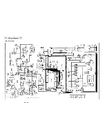
Page 19: ...16 Wiring Diagram MDF C2156VAN ...
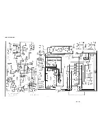
Page 20: ...17 MDF C2156VANC ...
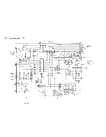
Page 21: ...18 Circuit Diagram ...
Page 22: ...19 CR Circuit Diagram ...